Information communication device and external device

a technology of information communication and external devices, applied in the field of cameras, can solve problems such as difficulty in making ligh

Active Publication Date: 2009-07-23
NIKON CORP
View PDF7 Cites 49 Cited by
  • Summary
  • Abstract
  • Description
  • Claims
  • Application Information

AI Technical Summary

Benefits of technology

[0014]According to the 7th aspect of the present invention, in the information communication device according to the 1st aspect, it is preferred that: the information communication device is a camera; the external device is an electronic flash unit; if a mode of the camera is set to a rear curtain sync mode in which the electronic flash unit is caused to emit light directly before a travel of a rear curtain of the shutter, the packet generation unit generates a light emission command packet that specifies a first light emission command without including the

Problems solved by technology

However, with such a prior art system, it has been difficult to make the light emission timings of the main electronic flash unit on the camera side and of the auxiliary electronic flash unit, that is an external device, agree

Method used


Image

  • Information communication device and external device
  • Information communication device and external device
  • Information communication device and external device

Examples


embodiment one

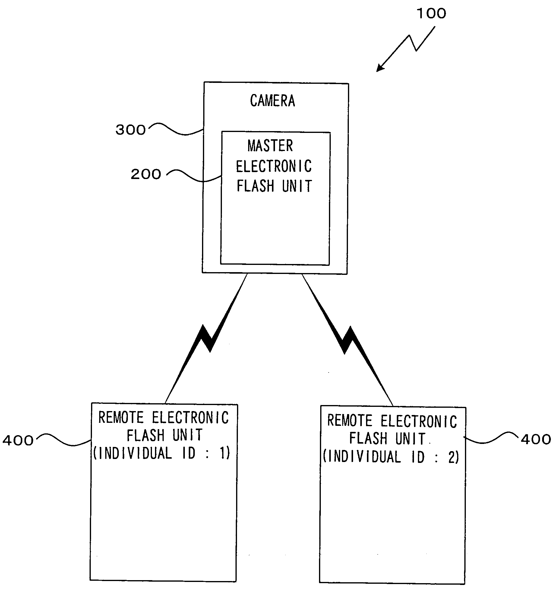
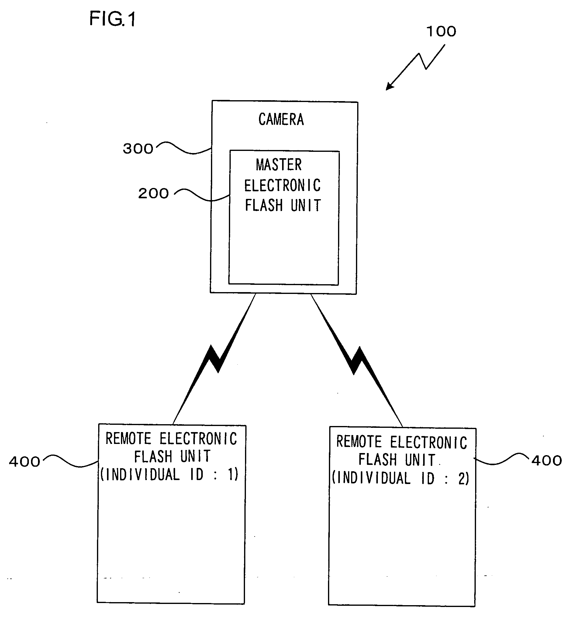
[0055]FIG. 1 is a block diagram showing the structure of one embodiment of a light emission control system according to the first embodiment. In this light emission control system 100, a camera 300 to which a master electronic flash unit 200 is mounted, and one or more external remote electronic flash units 400 are connected together using a wireless system such as a wireless LAN, Bluetooth, Zigbee or the like. However, it will be supposed that communication is not performed using any of these communication methods or communication standards, but by some idiosyncratic method. It should be understood that this light emission control system 100 includes one camera 300 to which the master electronic flash unit 200 is mounted, and at least one remote flash unit 400 that constitutes an external device. In the figure, there is shown a concrete example for the case consisting of one camera 300 and two remote flash units 400. The master electronic flash unit 200 may also be termed an inform...

embodiment two

[0146]In the first embodiment described above, it was arranged to command the emission of light by transmitting a light emission command packet from the master electronic flash unit 200 to the remote electronic flash unit 400. And, during the front curtain sync mode, data is included in the parameter 5g in this light emission command packet for designating the amount of light to be emitted by the remote electronic light emission device 400. Moreover, during the rear curtain sync mode, data is included in the parameter 5g for designating the amount of light to be emitted by the remote electronic light emission device 400, and data is included for designating a time period for the light emission to be continued, that specifies a time period during that it is necessary to keep on emitting light.

[0147]By contrast, in the second embodiment, the CPU 206m of the master electronic flash unit 200, before commanding the emission of light by transmitting the light emission command packet descr...


PUM


Abstract

An information communication device includes: a packet generation unit that generates a packet including timing data at an end of the packet for specifying to an external device a start timing for processing related to photography; a transmitting unit that transmits the packet to the external device by wireless communication; and a transmission control unit that changes a state of packet transmission by the transmission unit according to a start timing of the processing related to photography.

Description

[0001]This application is a continuation of International Application No. PCT / JP2007 / 070469 filed Oct. 19, 2007.INCORPORATION BY REFERENCE[0002]The disclosures of the following priority application and International Application are herein incorporated by reference: Japanese Patent Application No. 2006-285144, filed Oct. 19, 2006; and International Application No. PCT / JP2007 / 070469, filed Oct. 19, 2007.BACKGROUND OF THE INVENTION[0003]1. Field of the Invention[0004]The present invention relates to a camera for photographing images, and to an external device that is connected to the camera.[0005]2. Description of Related Art[0006]A wireless light supplementation system of the following type is, for example, known from Patent Reference #1. With this system, an auxiliary electronic flash unit detects light emission by a main electronic flash unit that is connected to the camera, and starts its own light emission (refer to Japanese Laid-Open Patent Publication H06-267682).SUMMARY OF THE ...

Claims


Application Information

Patent Timeline
IPC IPC(8): G03B17/00H04N5/225G03B15/03
CPCG03B15/05H04N5/2354H04N5/23203G03B17/18G03B2215/0557H04N23/66H04N23/74
Inventor OGASAWARA, AKIRA
Owner NIKON CORP
Why Eureka
Try Eureka