Portable coordinate measurement machine with integrated line laser scanner

a laser scanner and coordinate technology, applied in the field of coordinate measurement machines, can solve the problems of loss or at least diminished functionality of highly accurate single point probes, limited prior art devices,

Inactive Publication Date: 2009-07-23
FARO TECH INC
View PDF14 Cites 174 Cited by
  • Summary
  • Abstract
  • Description
  • Claims
  • Application Information

AI Technical Summary

Problems solved by technology

The prior art devices are limited in that they are capable of measuring only one point in space at a time.
However, such prior art devices are retrofit onto the existing articulated arms of portable CMM's and require external, high bandwidth data connections from the scanner to the host computer used to interpret the image data generated by the CCD as well as external connections to power supplies.
Furthermore, when the single-point probe is replaced by the line laser scanner retrofit, the highly accurate single point probe functionality is lost or at least diminished.

Method used


Image

  • Portable coordinate measurement machine with integrated line laser scanner
  • Portable coordinate measurement machine with integrated line laser scanner
  • Portable coordinate measurement machine with integrated line laser scanner

Examples


Embodiment Construction

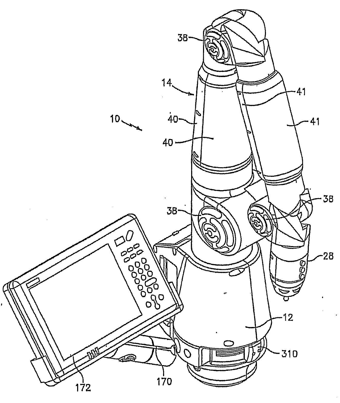
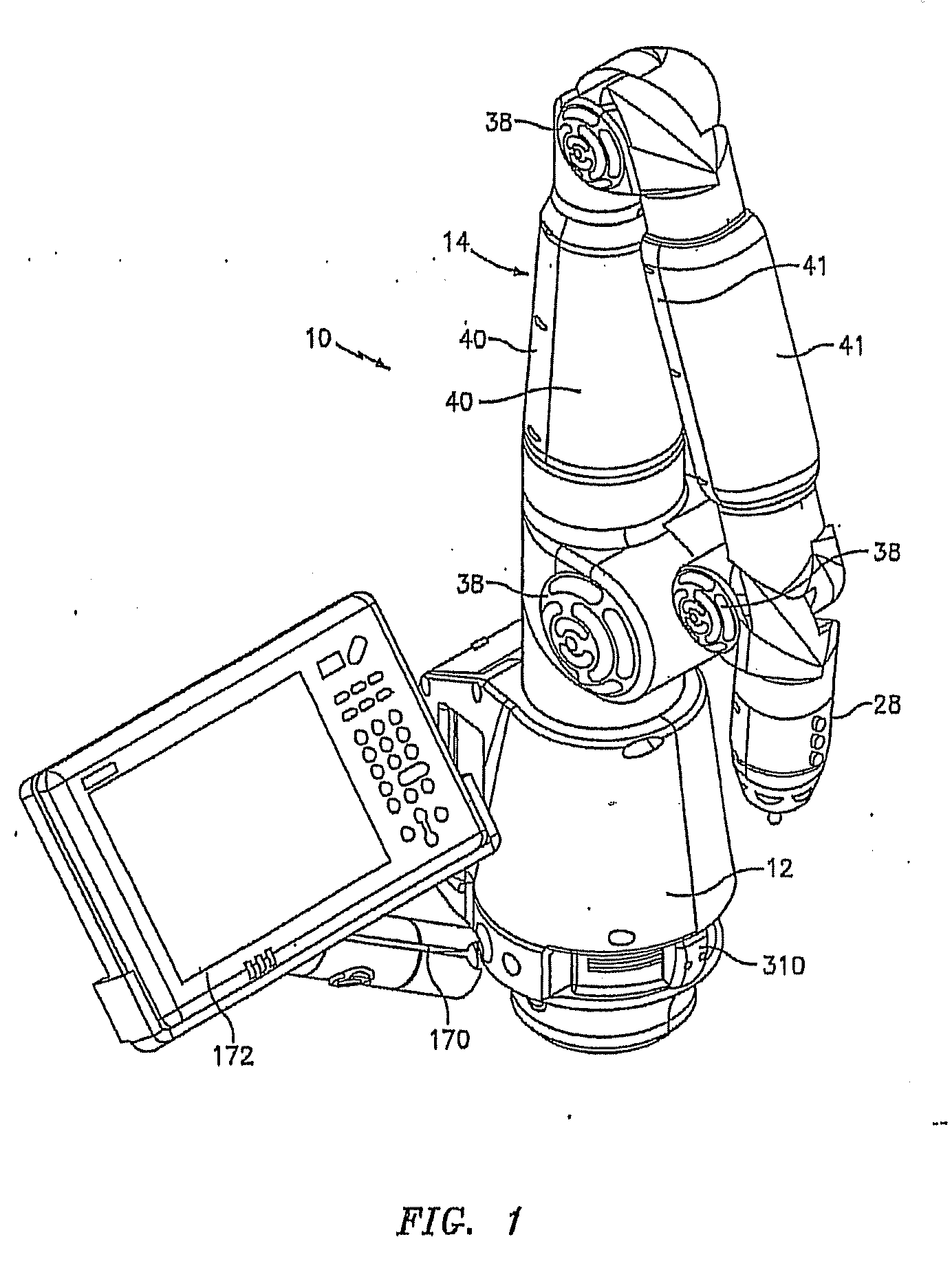
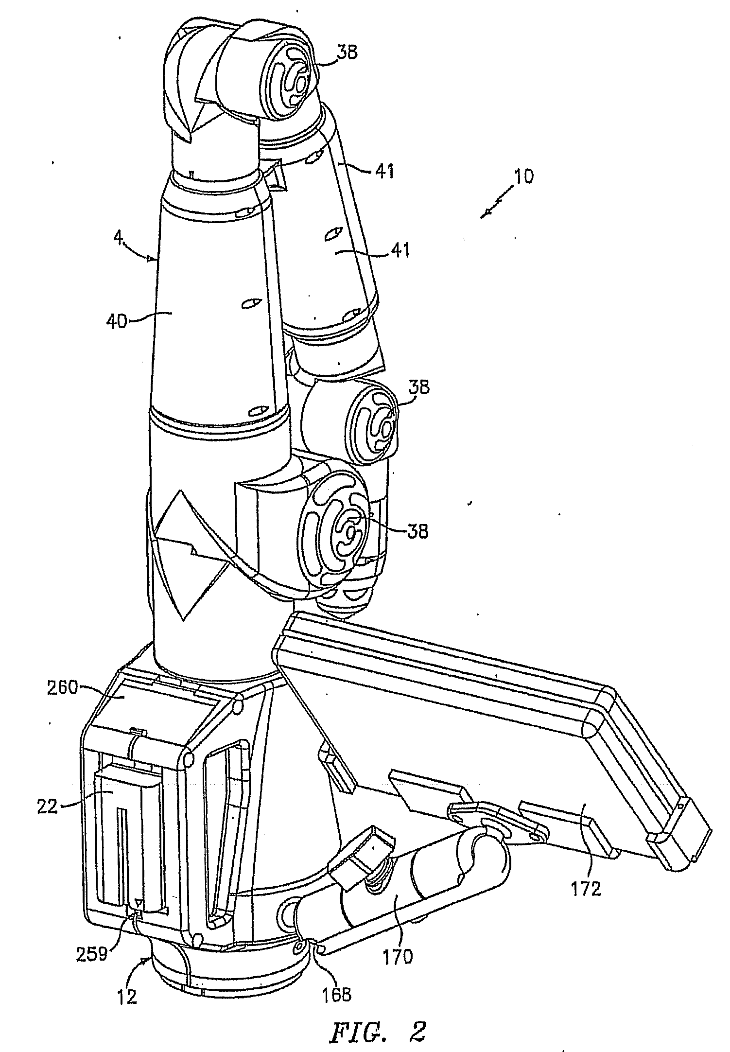
[0090]Referring first to FIGS. 1-3, the CMM of the present invention is shown generally at 10. CMM 10 comprises a multijointed, manually operated, articulated arm 14 attached at one end to a base section 12 and attached at the other end to a measurement probe 28. Arm 14 is constructed of basically two types of joints, namely a long joint (for swivel motion) and a short joint (for hinge motion). The long joints are positioned substantially axially or longitudinally along the arm while the short joints are preferably positioned at 90° to the longitudinal axis of the arm. The long and short joints are paired up in what is commonly known as a 2-2-2 configuration (although other joint configurations such as 2-1-2, 2-1-3, 2-2-3, etc. may be employed) Each of these joint pairs are shown in FIGS. 4-6.

[0091]FIG. 4 depicts an exploded view of the first joint pair, namely long joint 16 and short joint 18. FIG. 4 also depicts an exploded view of the base 12 including a portable power supply ele...


PUM


Abstract

A portable coordinate measurement machine for measuring the position of an object in a selected volume comprises includes an a positionable articulated arm having a plurality of jointed arm segments. The arm includes a measurement probe having an integrated line laser scanner mounted thereon. The laser may be a fiber coupled laser. Wireless data transfer and communication capability for the CMM is also possible.

Description

CROSS-REFERENCE TO RELATED APPLICATION[0001]This application is a continuation-in-part (CIP) application of application Ser. No. 11 / 765,726, filed Jun. 20, 2007. The Ser. No. 11 / 765,726 application is a continuation-in-part (CIP) of application Ser. No. 11 / 334,091 filed Jan. 18, 2007, which in turn was a continuation-in-part (CIP) of application Ser. No. 11 / 141,444 filed May 31, 2005, now U.S. Pat. No. 7,050,930, which in turn is a continuation application of application Ser. No. 10 / 366,678 filed Feb. 13, 2003 (now U.S. Pat. No. 6,965,843) and claims the benefit of provisional application Nos. 60 / 357,599 filed Feb. 14, 2002 and 60 / 394,908 filed Jul. 10, 2002. The contents of the Ser. No. 10 / 366,678 application, the Ser. No. 11 / 334,091 application, the Ser. No. 11 / 141,444 application, the Ser. No. 11 / 765,726 application, and both provisional applications above are hereby incorporated into the present CIP application by reference and domestic priority is claimed in the present CIP app...

Claims


Application Information

Patent Timeline
Patent Type & Authority Applications(United States)
IPC IPC(8): G06F15/00G01B5/008
CPCB25J9/1692G01B11/005G01B21/042G01C25/00G01B5/008G05B2219/37193G05B2219/40233G05B2219/45061G01B7/008G05B19/401
Inventor ATWELL, PAUL CHRISTOPHERBARBA, JACINT R.YORK, FREDERICK
Owner FARO TECH INC
Why Eureka
Try Eureka