Thrust reverser forming an adaptive nozzle

a technology of adaptive nozzles and thrust reversers, which is applied in the direction of machines/engines, mechanical equipment, and jet propulsion plants, etc., can solve the problems of no longer suitable and optimum cross sections of secondary exhaust nozzles, and achieve the effect of minimizing the impact of aerodynamic discontinuity

Inactive Publication Date: 2009-07-30
AIRCELLE
View PDF8 Cites 34 Cited by
  • Summary
  • Abstract
  • Description
  • Claims
  • Application Information

AI Technical Summary

Benefits of technology

[0017]Thus, by dividing the movable cowl into an internal portion and an external portion which can move independently of one another at least in part, it is possible to adapt the relative positions of the external portion and the internal portion so as to vary the cross section of the nozzle formed by the movable cowl by varying the length of the internal aerodynamic line of said movable cowl, both when the movable cowl is in a closed position and covers the deflection means and when the movable cowl is in an open position. In this way, it is easy to adapt the cross section of the exhaust nozzle formed by the movable cowl to the flight conditions so as to maintain an optimum configuration.
[0019]Advantageously, the external portion and the internal portion are separated at the location of a recess of an internal aerodynamic line of the movable cowl. This makes it possible to minimize the impact of the aerodynamic discontinuity that is represented by the interruption between the external portion and the internal portion.

Problems solved by technology

However, there remains a problem of adapting the powerplant to the various flight phases which it encounters, in particular the aircraft takeoff and landing phases for which the optimum cross sections of the secondary exhaust nozzle that have been defined for cruise flight conditions are no longer suited.

Method used


Image

  • Thrust reverser forming an adaptive nozzle
  • Thrust reverser forming an adaptive nozzle
  • Thrust reverser forming an adaptive nozzle

Examples


first embodiment

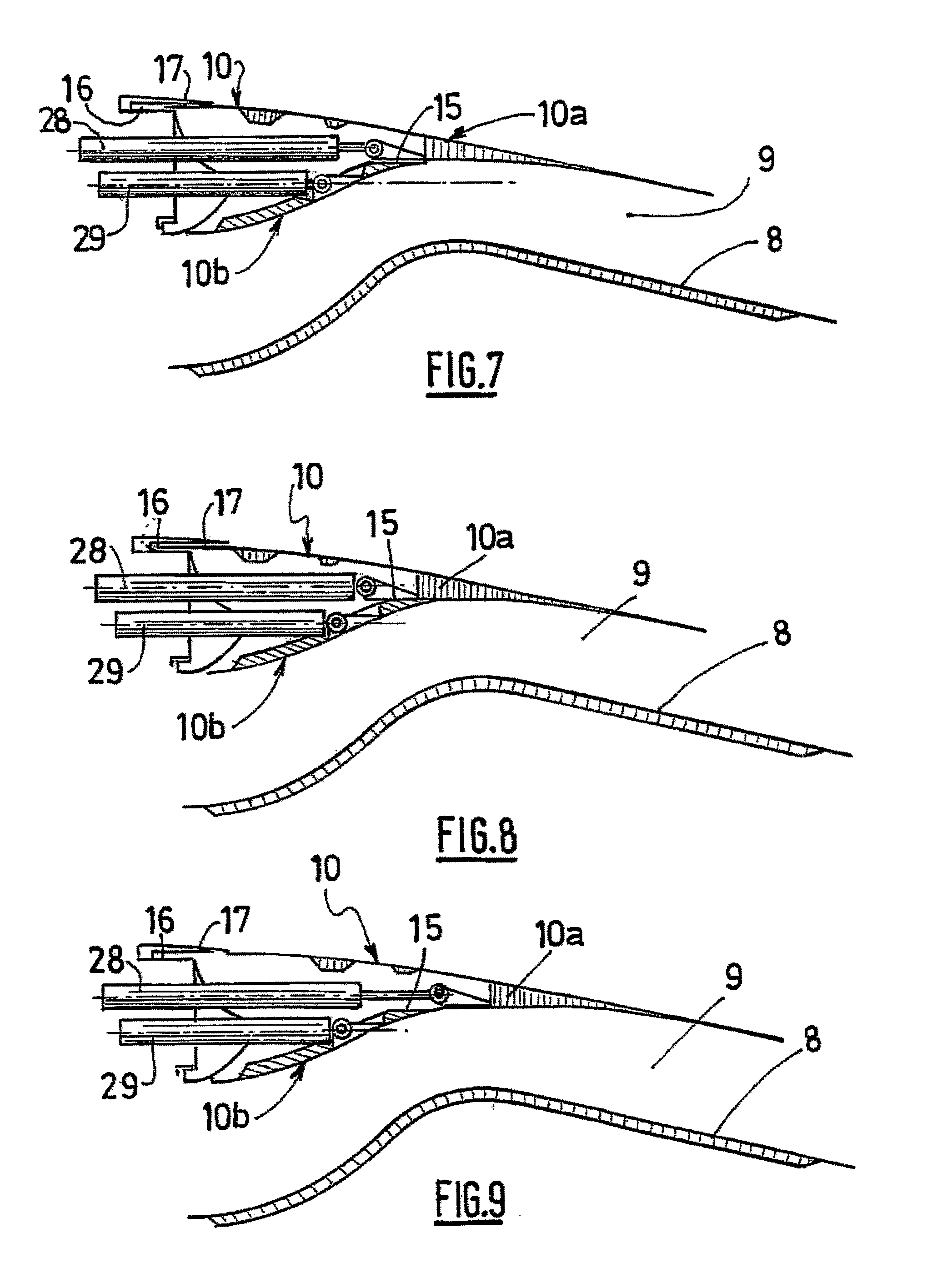
[0072] represented in FIGS. 6 to 10, each of the external 10a and internal 10b portions is connected to a ram 28, 29 of pneumatic, hydraulic or electric type, preferably electric type, able to allow a longitudinal movement of the corresponding external 10a or internal 10b portion.

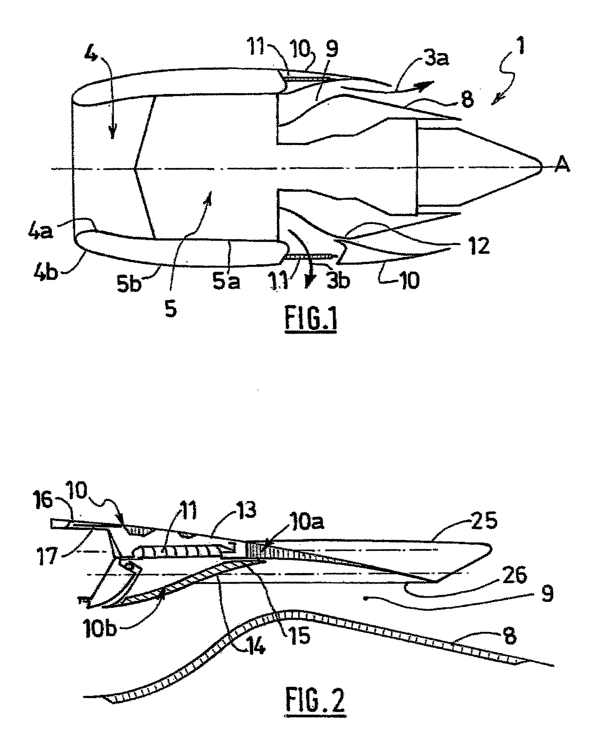
[0073]FIG. 7 shows the relative positions of the external portion 10a and the internal portion 10b of the movable cowl 10 when the latter is in a closed position in which it covers the deflection cascades 11 and has a conventional exhaust nozzle cross section.

[0074]The cross section of the nozzle can be easily modified by moving the external portion 10a and the internal portion 10b independently by means of their respective rams 28, 29.

[0075]FIG. 8 represents a thrust reverser in a closed position forming an exhaust nozzle of reduced cross section, the ram 28 of the external portion 10a being retracted to a maximum.

[0076]FIG. 9 represents a thrust reverser in a closed position forming an exhaust nozzle with...

second embodiment

[0081] represented in FIG. 12, the actuating means comprise a telescopic ram 30 having a first rod 30a connected to the external portion 10a and a second rod 30b connected to the internal portion 10b. As above, this telescopic ram 30 can be hydraulic, pneumatic or electric, preferably electric.

[0082]The assembly is supplemented by means 31 (means not shown) for locking the external 10a and internal 10b portions.

[0083]In the case of a hydraulic ram, the operations of reducing and increasing the cross section of the exhaust nozzle are carried out by means of a hydraulic pressure acting on the cross sections of the rods 30a, 30b. First of all, the first rod 30a, connected to the external portion 10a, is the one which is actuated. At the end of the retreating movement of the first rod 30a, the latter butts against the second rod 30b which in turn drives along the internal portion 10b of the movable cowl 10 after unlocking the means 31 for locking said internal portion 10b. The internal ...


PUM


Abstract

The present invention relates to a thrust reverser for the nacelle of a turbojet engine comprising, on the one hand, means (11) for deflecting at least some of an air flow of the turbojet engine and, on the other hand, at least one hood (10) able to move translationally in a direction substantially parallel to a longitudinal axis of the nacelle and able to switch alternately from a closed position in which it ensures the aerodynamic continuity of the nacelle and covers the deflection means, and an open position in which it opens a passage in the nacelle and uncovers the deflection means, characterized in that the moving hood comprises at least one outer part (10a) having a downstream extension forming a nozzle and at least one internal part (10b) each of which parts is mounted such that it is translationally mobile and is connected to at least one actuating means able to allow it to be moved, each independently of the other, or together, in a substantially longitudinal direction of the nacelle. The present invention also relates to a turbojet engine nacelle comprising such a thrust reverser.

Description

TECHNICAL FIELD OF THE INVENTION[0001]The present invention relates to a thrust reverser for a turbine engine nacelle comprising, on the one hand, means for deflecting at least a fraction of an air stream of the turbine engine and, on the other hand, at least one cowl which can move translationally in a substantially longitudinal direction of the nacelle and which is able to switch alternately from a closed position in which it provides aerodynamic continuity of the nacelle and covers the deflection means, to an open position in which it opens a passage in the nacelle and uncovers the deflection means. The present invention also relates to a turbine engine nacelle comprising such a thrust reverser.BRIEF DESCRIPTION OF RELATED ART[0002]An aircraft is propelled by a number of turbine engines each housed in a nacelle which also accommodates a collection of auxiliary actuating devices associated with the operation thereof and performing various functions when the turbine engine is opera...

Claims


Application Information

Patent Timeline
Patent Type & Authority Applications(United States)
IPC IPC(8): F02K3/02
CPCF02K1/09F05D2270/64F05D2270/62F02K1/72
Inventor VAUCHEL, GUY BERNARDBAUDU, PIERRE ANDRE MARCEL
Owner AIRCELLE
Why Eureka
Try Eureka