
Open Loop Gas Burner

Inactive Publication Date: 2009-07-30
GARLAND COMML IND
View PDF73 Cites 4 Cited by
  • Summary
  • Abstract
  • Description
  • Claims
  • Application Information

AI Technical Summary

Benefits of technology

[0016]These and other advantages and benefits of the present disclosure are provided by a gas burner having an air-gas mixture distribution section formed in an open loop geometry. The gas burner can have any number of sides designed to provide an open loop geometry. In one embodiment, the gas burner has a first side, a second side and a third side. The air-gas mixture distribution section has a top heating surface. A plurality of ports are disposed on the top heating surface. The air-gas mixture distribution section has an inlet disposed thereon and a distribution diffuser mounted therein.

Problems solved by technology

Traditional gas burners exhibit performance deficiencies due to non-uniform flame characteristics, non-uniform heating conditions and uneven pressure distribution that are inherent with the design of the burner.
Non-uniform flame characteristics of traditional gas burners often create the non-uniform heating conditions on the cooking surface.
These non-uniform heating conditions manifest themselves as localized hot or cold spots along the cooking surface resulting in unpredictable and inconsistent cooking.
Non-uniform flame characteristics are primarily a result of the geometry of the gas burner.
The migration of the flue gas to the back end results in an excess heat build-up in that region and consequently, there are non-uniform flame characteristics and non-uniform heating conditions.
The uneven pressure distribution in traditional gas burners is primarily a result of the positioning of the diffuser directly under the ports of the burner.
This configuration does not provide a space for the gas to even out the pressure above the diffuser because of the close proximity of the ports.
The uneven pressure distribution created by the positioning of the diffuser can also result in popping, flashback, or excess flame lifting because of the non-uniform distribution of gas throughout the distribution section of the gas burner.
Furthermore, the location of the diffuser and the inlet in traditional gas burners gives the burner a front to rear overall dimension that can lead to packaging difficulties.

Method used


Image

  • Open Loop Gas Burner
  • Open Loop Gas Burner
  • Open Loop Gas Burner

Examples


Embodiment Construction

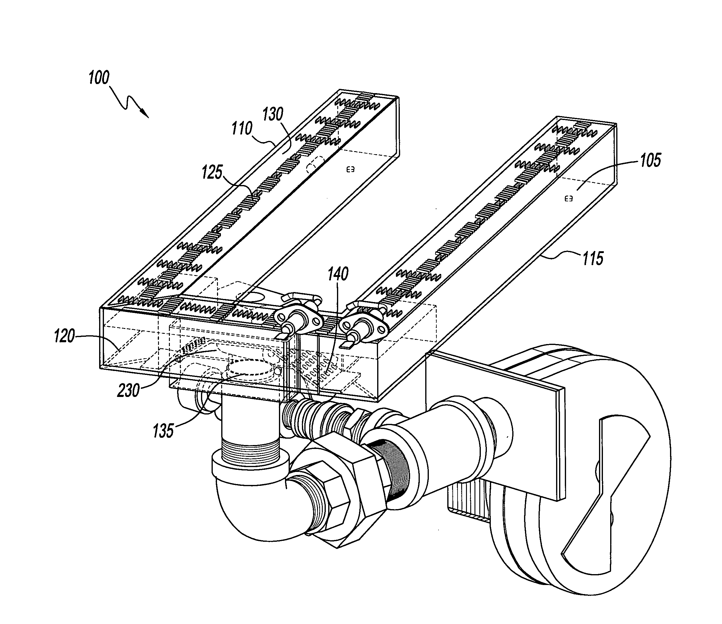
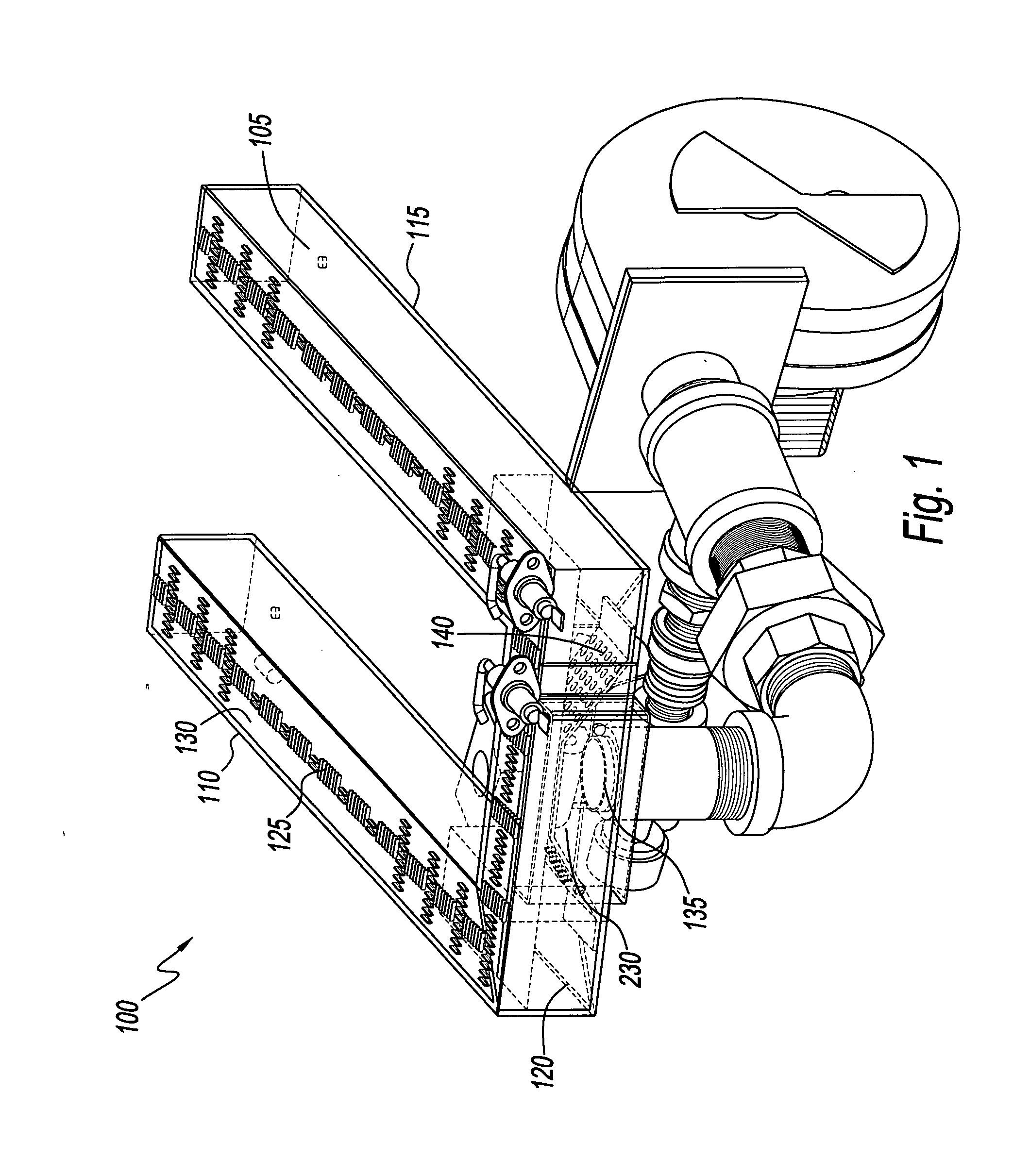
[0025]Referring to the drawings and, in particular, FIG. 1, a gas burner generally referred to by reference number 100 is shown. In one embodiment, gas burner 100 has an air-gas mixture distribution section 105. Air-gas mixture distribution section 105 has an open loop, or U-shaped geometry, that has a plurality of sides. In one embodiment, air-gas mixture distribution section 105 has two long sides 110 and 115 and one short side 120. A plurality of apertures or ports 125 are disposed on a top heating surface 130 of air-gas mixture distribution section 105 that in the present configuration is substantially flat. Gas burner 100 further includes an inlet 135 at an end of air-gas mixture distribution section 105. A distribution diffuser 140 is provided near inlet 135.

[0026]The gas burner 100 of the present disclosure advantageously utilizes heat more efficiently because there are no burner ports disposed at the back end of the burner and thus, there is an outlet for flue gases to escap...


PUM


Abstract

A gas burner has an air-gas mixture distribution section with an open loop geometry and a plurality of sides. The air-gas mixture distribution section has a top heating surface and a plurality of ports are disposed on the top heating surface. An inlet is disposed on one of the plurality of sides of the air-gas mixture distribution section and a distribution diffuser is mounted inside the air-gas mixture distribution section.

Description

CROSS-REFERENCE TO RELATED APPLICATIONS[0001]The present application claims priority to U.S. Provisional Application No. 61 / 011,250, filed on Jan. 18, 2008.BACKGROUND OF THE INVENTION[0002]1. Field of the Invention[0003]The present disclosure relates to a gas burner having an open loop geometry that achieves uniform or distributed flame characteristics, uniform or distributed heating conditions and an even pressure distribution throughout the burner.[0004]2. Description of Related Art[0005]Traditional gas burners are used in grill and griddle assemblies to heat a cooking surface. There are two types of gas burners that are commonly used that include an atmospheric burner and a powered burner. The atmospheric burner relies solely on static pressure of the gas from a gas supply to provide an air-gas mixture at various burner ports where the air-gas mixture may be ignited to create a flame. The powered burner utilizes a fan or blower and is connected to a supply of gas prior to an inle...

Claims


Application Information

Patent Timeline
IPC IPC(8): F24C3/00
CPCF24C3/085F23D14/70F23D14/34F23D14/02
Inventor NEVAREZ, ROBERTOJONES, DOUGLAS S.
Owner GARLAND COMML IND
Features
  • Generate Ideas
  • Intellectual Property
  • Life Sciences
  • Materials
  • Tech Scout
  • Unparalleled Data Quality
  • Higher Quality Content
  • 60% Fewer Hallucinations
Learn More