
Fire suppression fluid circulation system

a technology of fluid circulation system and fire suppression, which is applied in the direction of couplings, cleaning using liquids, instruments, etc., can solve the problem of large quantity of water

Inactive Publication Date: 2009-07-30
AGF MFG
View PDF17 Cites 50 Cited by
  • Summary
  • Abstract
  • Description
  • Claims
  • Application Information

AI Technical Summary

Benefits of technology

[0002]In a typical fire suppression water sprinkler system as installed in many buildings, an array of individual fire sprinklers is supplied with water through a main conduit and various branch conduits. The individual fire sprinklers are generally provided with a member that melts when the ambient temperature reaches a predetermined level indicative of a fire. The melting of the member opens a fire sprinkler to spray water in order to suppress the fire. The individual fire sprinklers are provided with meltable members so that the spray of water will hopefully be limited to the region of the building where the fire is present. In this way, the extent of water damage may be minimized.
[0007]The construction industry has increasingly recognized the environmental, economic and health and community benefits of providing so-called green buildings. The establishment of the leadership in energy and environmental design (LEED) Green Building Rating System™ recognizes that reducing water consumption provides environmental, economic and health and community benefits. These benefits include conserving natural resources, reducing operating costs, enhancing asset value and profits and minimizing the strain on local infrastructure.
[0009]It is another object of the preferred embodiments of the present invention to provide a circulation valve and tank arrangement whereby fluid used when a fire suppression system is tested is not discarded as waste.
[0011]It is another object of the preferred embodiments of the present invention to provide methods whereby fluid used when a fire suppression system is tested is not discarded as waste.

Problems solved by technology

Although an individual test of a fire suppression fluid flow sensor may require 10 to 12 gallons, in a large multi-story building the testing procedure results in the use of a large quantity of water that is ultimately released into the waste water system.

Method used


Image

  • Fire suppression fluid circulation system
  • Fire suppression fluid circulation system
  • Fire suppression fluid circulation system

Examples


Embodiment Construction

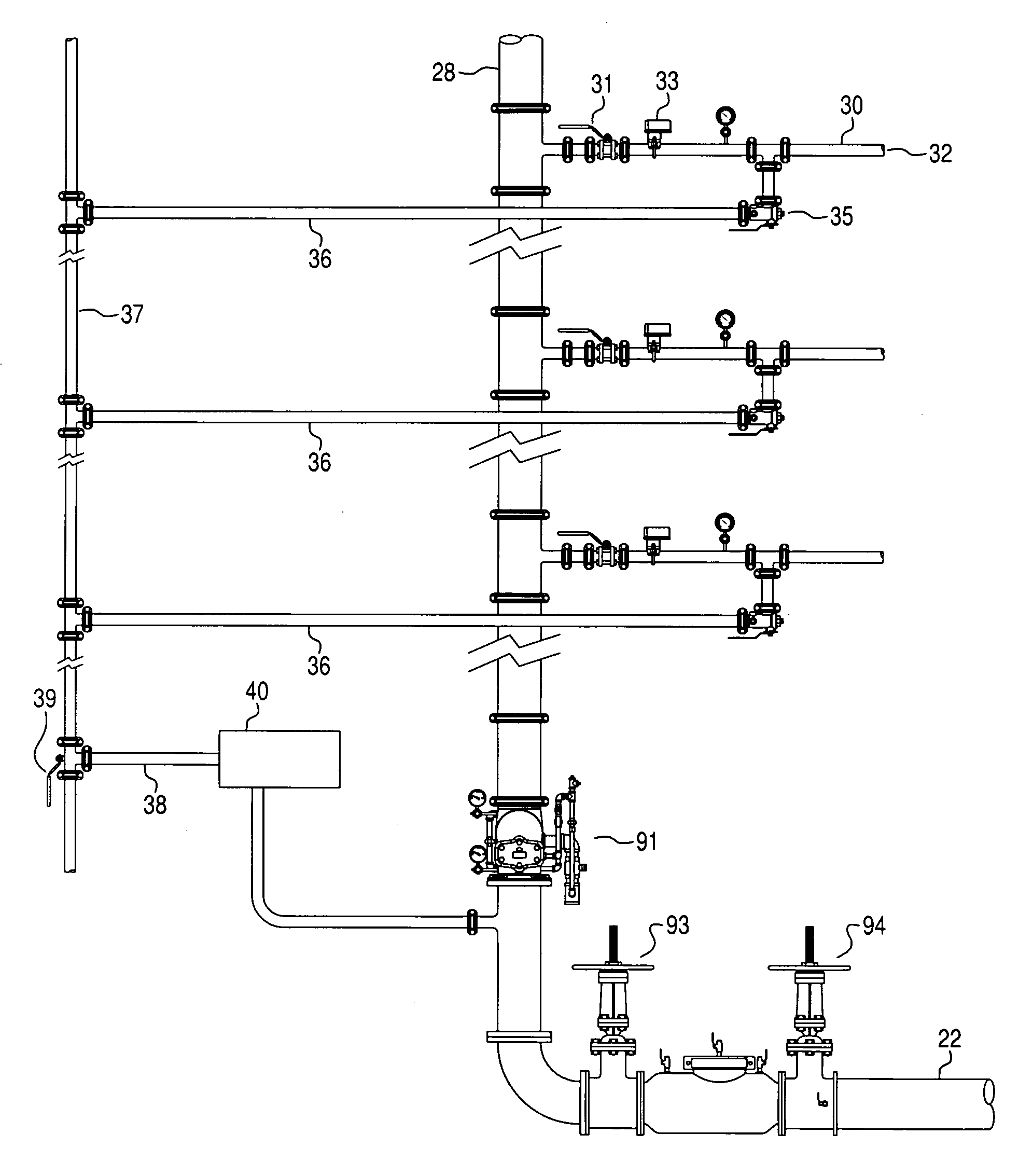
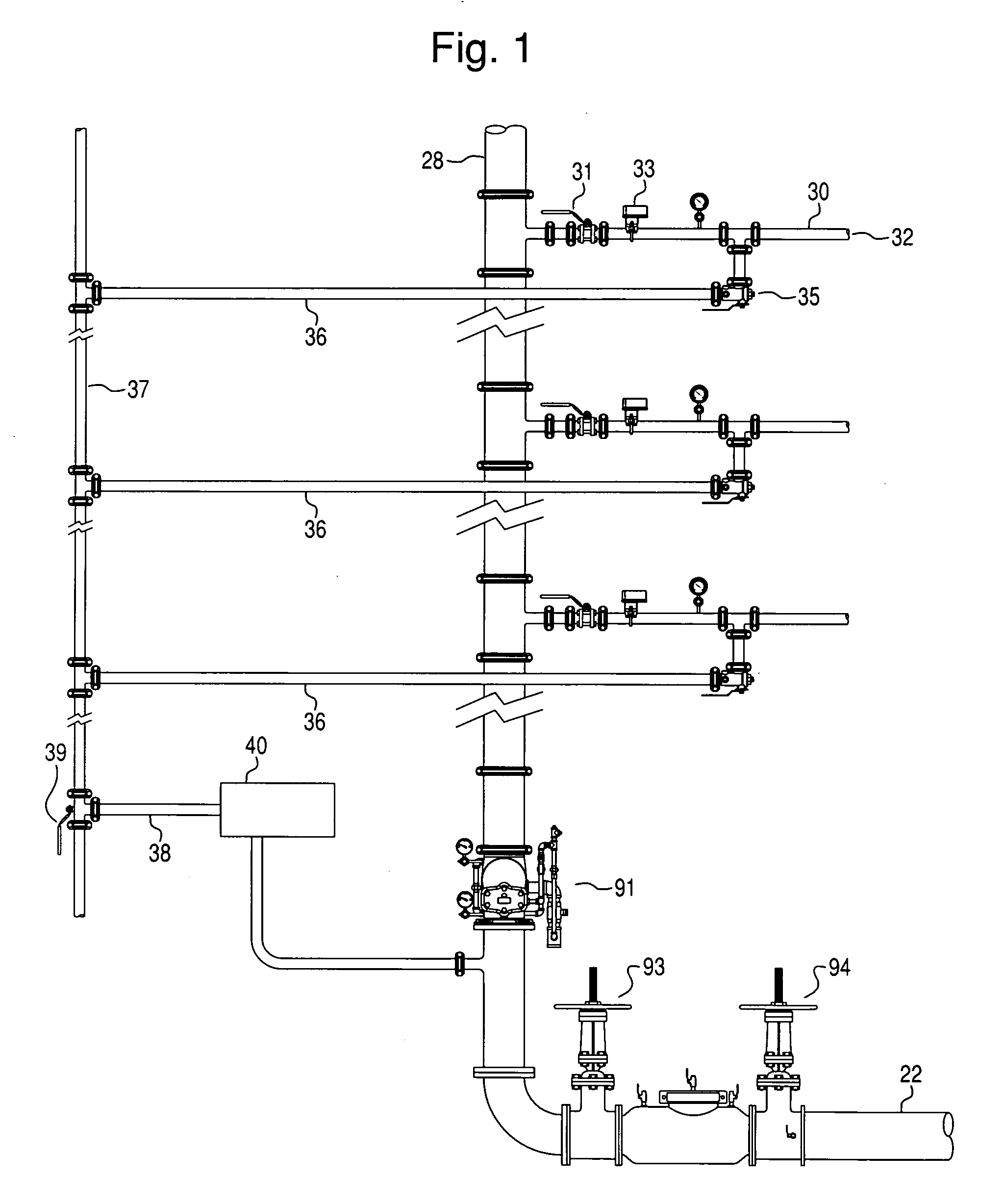
[0016]With reference to FIG. 1, a supply riser 28 receives a supply of fire suppression fluid, such as water, from an incoming supply 22 which is typically connected to a municipal water supply. The supply riser 28 has a plurality of branch conduits 30 including a number of sprinkler heads 32. Typically, a supply valve 31 either for an entire fire suppression system or for a particular floor or for a portion of the system is provided from the supply riser 28. The fluid is provided in the supply riser 28 at a pressure high enough to properly supply and operate the system. In some systems the municipal water pressure may be sufficient. Typically, in multi-story hi-rise buildings there will be a pressure loss of 5 psi per story. Therefore it may be necessary to provide a pump to bring and maintain the water to a sufficient operating pressure.

[0017]During testing of the typical fire suppression system, the fire suppression fluid is permitted to flow at least through the portion of a bra...


PUM


Abstract

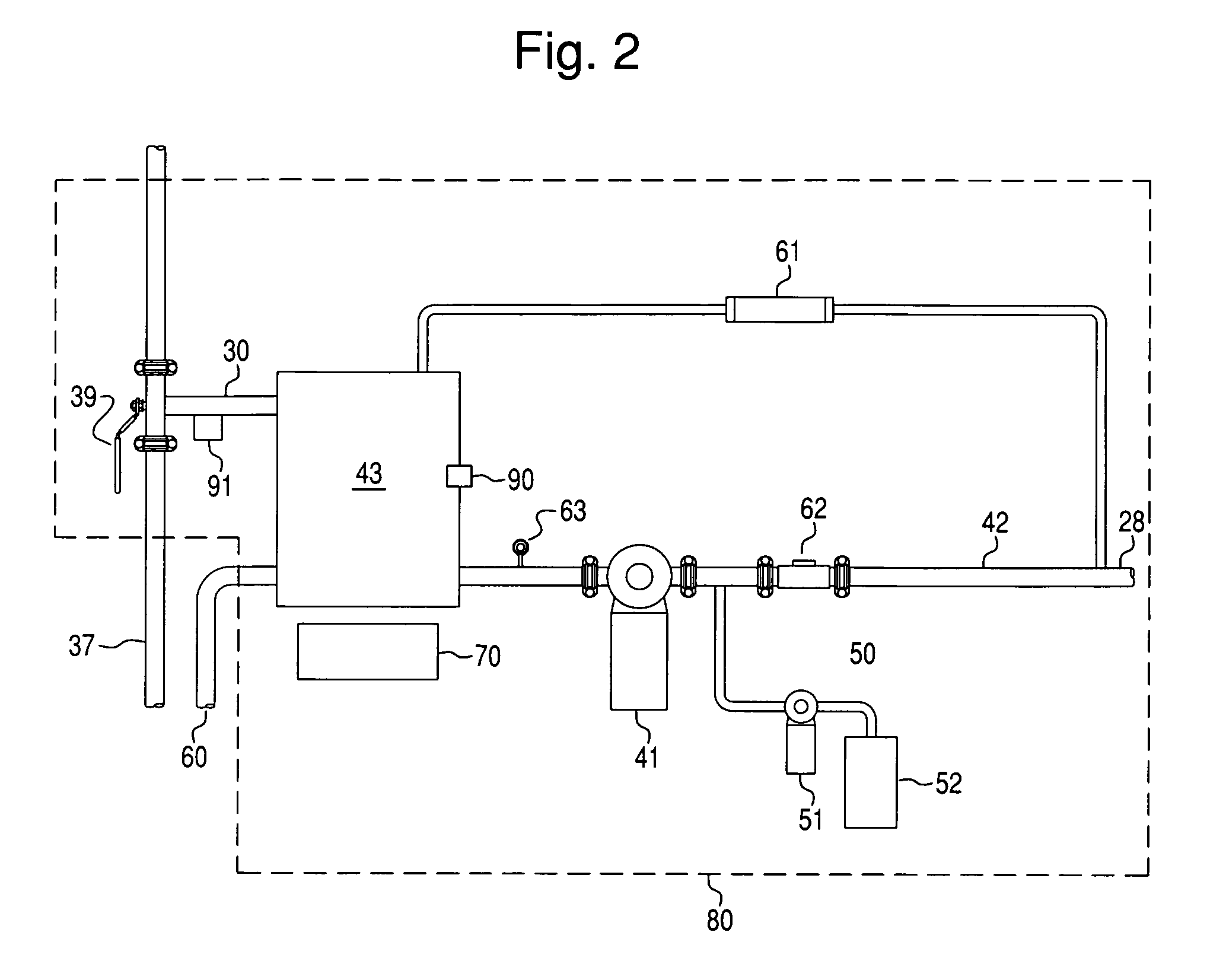
An arrangement for testing a fire suppression sprinkler system includes a supply conduit for supplying a fire suppression fluid to a plurality of sprinklers. A sensor senses a flow of fire suppression fluid through the supply conduit. A drain conduit drains fire suppression fluid when the fire suppression system is tested. A drain valve controls the flow of the fire suppression fluid so that when the fire suppression system is tested the fire suppression fluid is controlled to enter the drain conduit. A fire suppression fluid collection tank collects the fire suppression fluid which has entered the drain conduit for reintroducing the collected fire suppression fluid to the supply conduit. A circulation valve controls the flow of the fire suppression fluid so that when the fire suppression system is tested the fire suppression fluid enters the fire suppression fluid collection tank.

Description

BACKGROUND AND SUMMARY[0001]The present invention relates generally to testing fire suppression fluid sprinkler systems, and in particular the testing of flow switches in fire suppression fluid sprinkler systems.[0002]In a typical fire suppression water sprinkler system as installed in many buildings, an array of individual fire sprinklers is supplied with water through a main conduit and various branch conduits. The individual fire sprinklers are generally provided with a member that melts when the ambient temperature reaches a predetermined level indicative of a fire. The melting of the member opens a fire sprinkler to spray water in order to suppress the fire. The individual fire sprinklers are provided with meltable members so that the spray of water will hopefully be limited to the region of the building where the fire is present. In this way, the extent of water damage may be minimized.[0003]Such fire suppression systems also oftentimes have a switch or sensor that detects the...

Claims


Application Information

Patent Timeline
IPC IPC(8): A62C37/50G01M19/00G01M99/00
CPCA62C37/50A62C35/68Y10T137/0318Y10T137/0424Y10T137/85954Y10T137/87265
Inventor MCHUGH, GEORGE J.
Owner AGF MFG
Learn More