Frictional engaging piston and spring seat

Active Publication Date: 2009-07-30
TOYOTA JIDOSHA KK +1
View PDF7 Cites 9 Cited by
  • Summary
  • Abstract
  • Description
  • Claims
  • Application Information

AI Technical Summary

Benefits of technology

[0009]This invention thus provides a more durable frictional engaging piston that has a mounting hole for a return spring, and a spring seat which fits together with this frictional engaging piston and can be arranged so as not to interfere with another member.

Problems solved by technology

Also, stress concentrates at the gaps between multiple pressure apply portions so durability is insufficient.
However, even with the structure described above, stress still tends to concentrate at the partially removed region.
However, in this structure, when the mounting holes are provided in the portion where the pressure apply portion is continuously formed, the mounting holes make the pressure apply portion, which is already weaker than the other portion in the partially removed region as described above, even thinner.
As a result, those portions are much weaker than the other portions so the durability of the piston decreases, thus increasing the likelihood of cracking.

Method used


Image

  • Frictional engaging piston and spring seat
  • Frictional engaging piston and spring seat
  • Frictional engaging piston and spring seat

Examples


Embodiment Construction

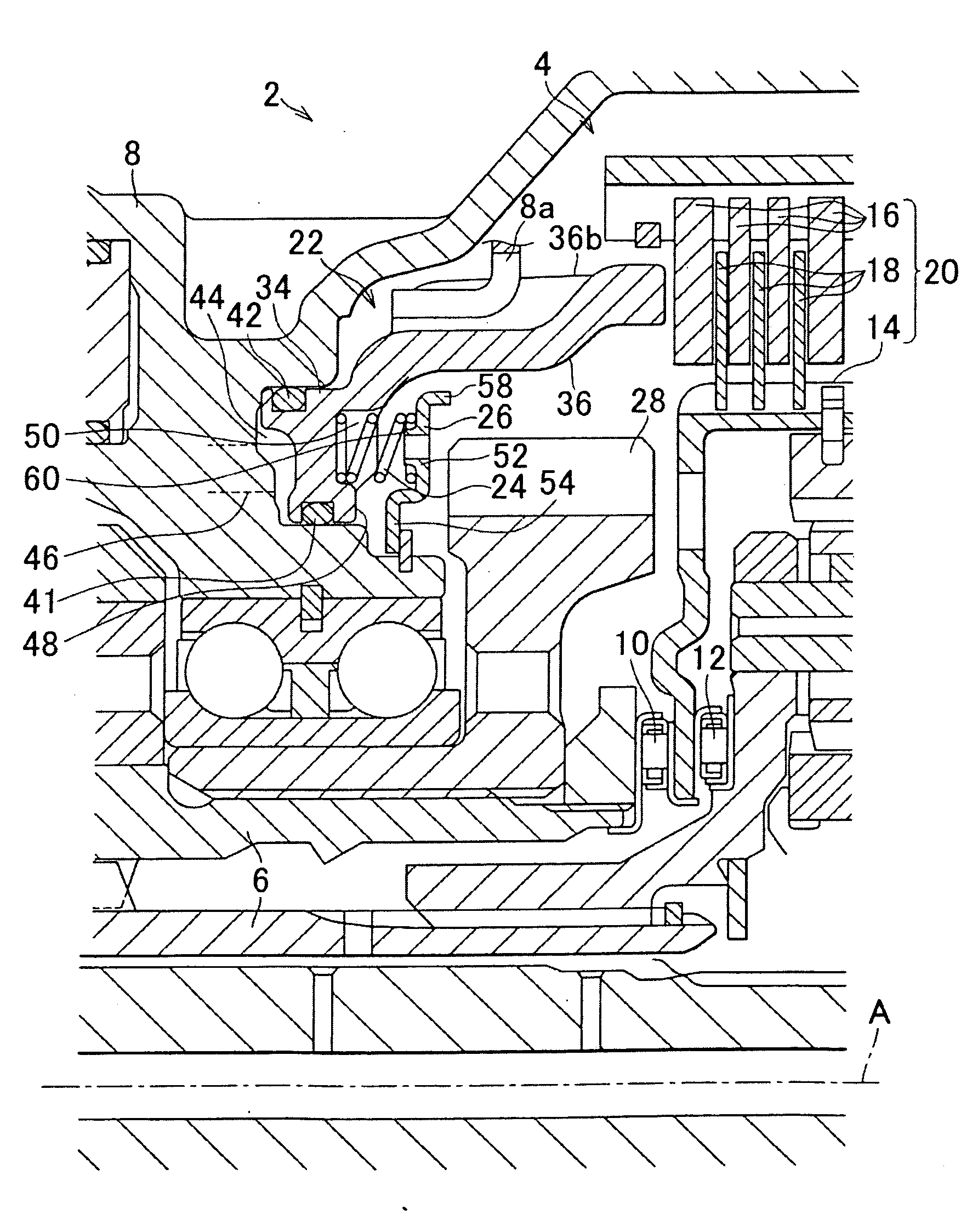
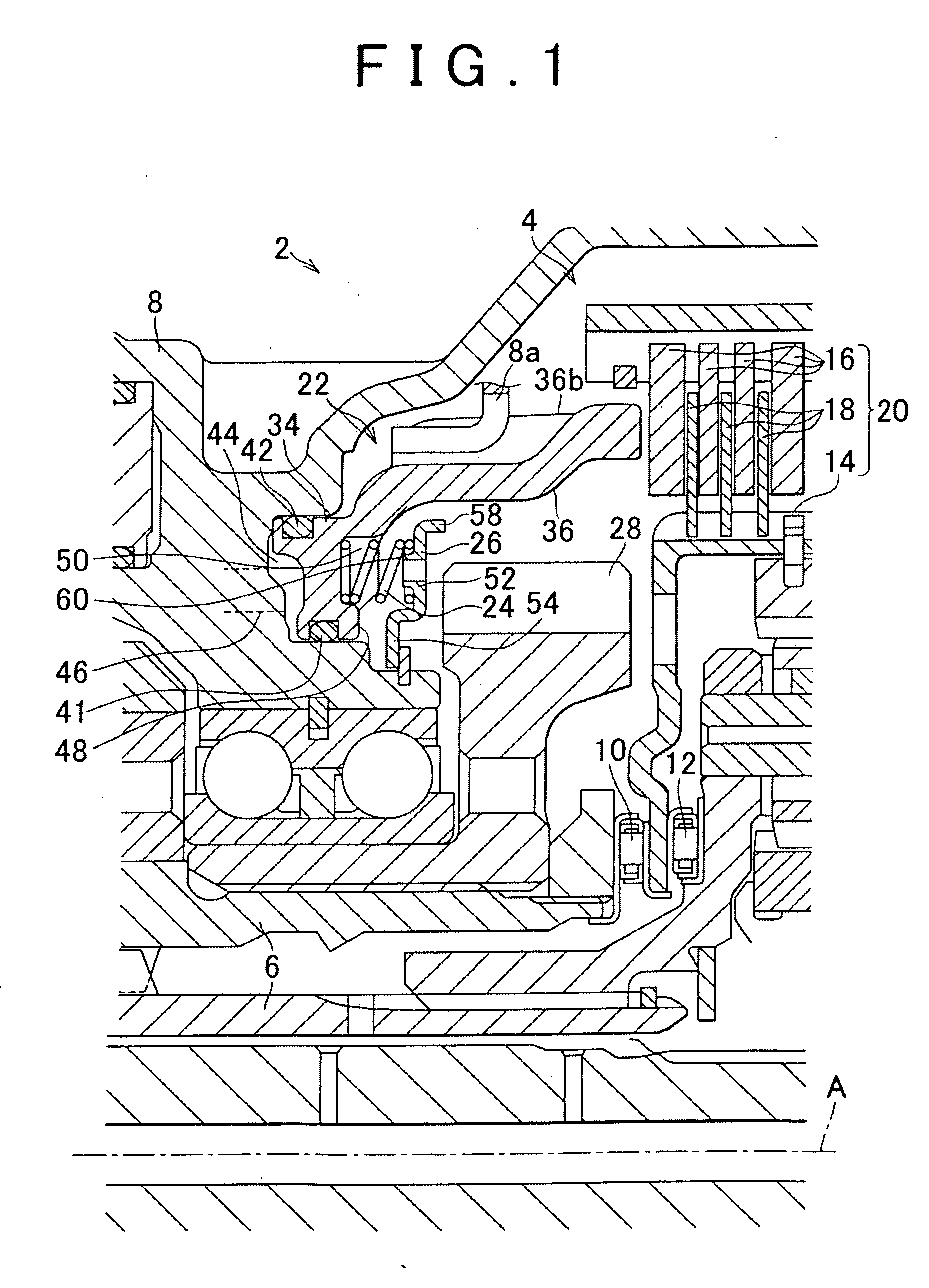
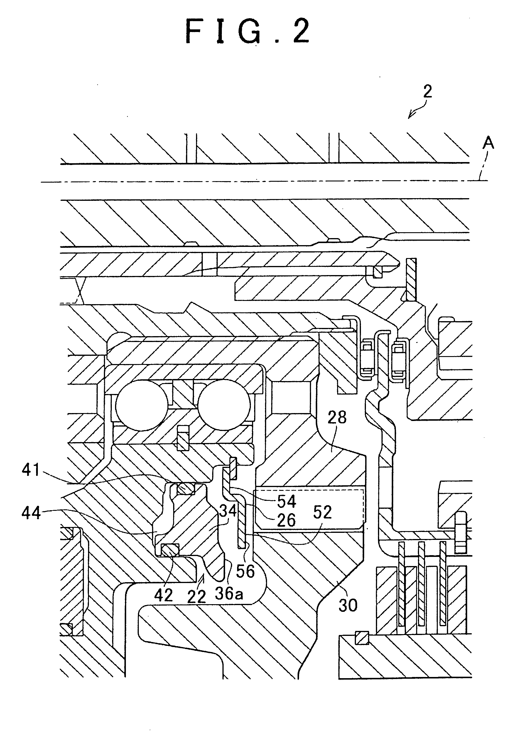
[0052]FIGS. 1 and 2 are sectional views of some of the main portions of the internal structure, in this case, the structure near a brake 4, of an automatic transmission 2 according to a first example embodiment of the invention described above. FIGS. 1 and 2 show the sectional structure at different phases with respect to a central axis A.

[0053]The automatic transmission 2 is a planetary gear type automatic transmission for a vehicle. The automatic transmission 2 is arranged between an internal combustion engine and driving wheels, and transmits output from the internal combustion engine to the driving wheels via a torque converter. The brake 4 is connected via two one-way clutches 10 and 12, between a housing 8 and a support shaft 6 that is connected to a sun gear. This brake 4 mainly includes i) a frictional engagement portion 20 (which is an example of the frictional engagement element of the invention) which is made up of a clutch hub 14, separator plates 16, and friction plates...


PUM


Abstract

An annular frictional engaging piston includes an annular pressure apply portion which pushes a frictional engagement element in an axial direction against urging force of a return spring that urges in a direction opposite the frictional engagement element, and which has a cutout portion where a portion in the circumferential direction has been removed to avoid interference between the piston and another member. A partially removed region is provided, and a mounting hole for mounting the return spring on the piston is provided in a region other than the partially removed region.

Description

INCORPORATION BY REFERENCE[0001]The disclosure of Japanese Patent Application No. 2008-016520 filed on Jan. 28, 2008, including the specification, drawings and abstract is incorporated herein by reference in its entirety.BACKGROUND OF THE INVENTION[0002]1. Field of the Invention[0003]The invention relates to an annular frictionally engaging piston that pushes, with an annular pressure apply portion, a frictional engagement element in the axial direction against urging force of a return spring that applies urging force in the direction opposite the frictional engagement element. The invention also relates to a spring seat for the return spring that is arranged opposing this frictionally engaging piston in the axial direction.[0004]2. Description of the Related Art[0005]Japanese Patent Application Publication No. 7-224911 (JP-A-7-224911) and Japanese Patent Application Publication No. 2000-81119 (JP-A-2000-81119) describe technology in which a frictional engagement element, such as a ...

Claims


Application Information

Patent Timeline
IPC IPC(8): F16D25/06F16D25/12F16H57/02F16H57/028F16H57/029F16H57/03F16H57/08
CPCF16D2048/0212F16D25/0638
Inventor HARASHIMA, TERASUYAMAGUCHI, SHUNDOU
Owner TOYOTA JIDOSHA KK
Why Eureka
Try Eureka