Dielectric enhanced partial thread spark plug

a technology of partial thread and spark plug, which is applied in the field of spark plugs, can solve the problems of less available volume for internal components, minimal available space for engine components, and small engines, and achieve the effect of improving heat resistance and enhancing spark plugs

Active Publication Date: 2009-07-30
BMO HARRIS BANK N A AS SUCCESSOR COLLATERAL AGENT +1
View PDF13 Cites 17 Cited by
  • Summary
  • Abstract
  • Description
  • Claims
  • Application Information

AI Technical Summary

Benefits of technology

[0005]In accordance with one exemplary embodiment of the invention, an enhanced spark plug is provided. The enhanced spark plug has an improved heat resistance. The spark plug includes a metal shell having a main body portion. The main body portion includes a first end, a second end and an intermediate section that collectively define an interior cavity. The intermediate section includes the intermediate section including a first unthreaded zone defining a first diametric portion and a second unthreaded zone adjacent to the first unthreaded zone defining a second diametric portion, the first diametric portion having an inner periphery greater than an inner periphery of the second diametric portion, the metal shell further comprising a third threaded zone adjacent to the second unthreaded zone and a fourth unthreaded zone adjacent the third threaded zone, the third threaded zone defining a third diametric portion having an inner periphery less than the inner periphery of the second diametric portion and the fourth unthreaded zone defining a fourth diametric portion having an inner periphery, the inner periphery of the fourth diametric portion being less than the inner periphery of the third diametric portion, wherein the interior cavity has a stepped configuration defined by the inner periphery of the first, second, third and fourth diametric portions; an insulator disposed in the metal shell, the insulator having a first end portion extending from the first

Problems solved by technology

Smaller engines, particularly those employed in compact motor vehicles, have minimal available space for engine comp

Method used


Image

  • Dielectric enhanced partial thread spark plug
  • Dielectric enhanced partial thread spark plug
  • Dielectric enhanced partial thread spark plug

Examples


Embodiment Construction

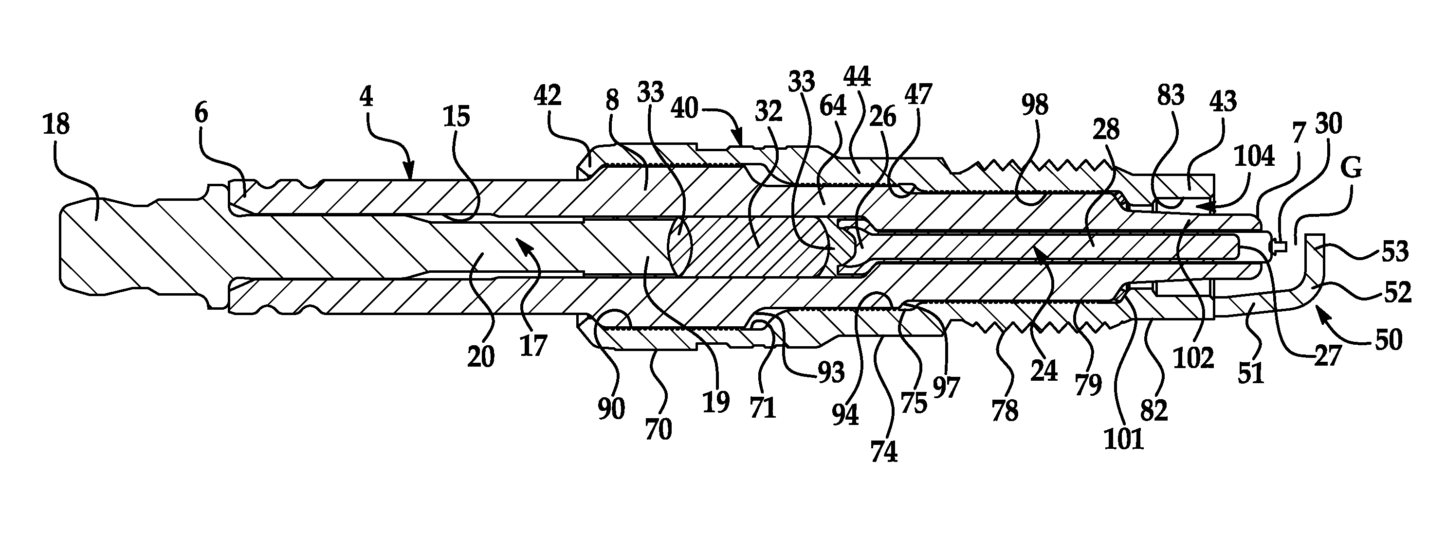
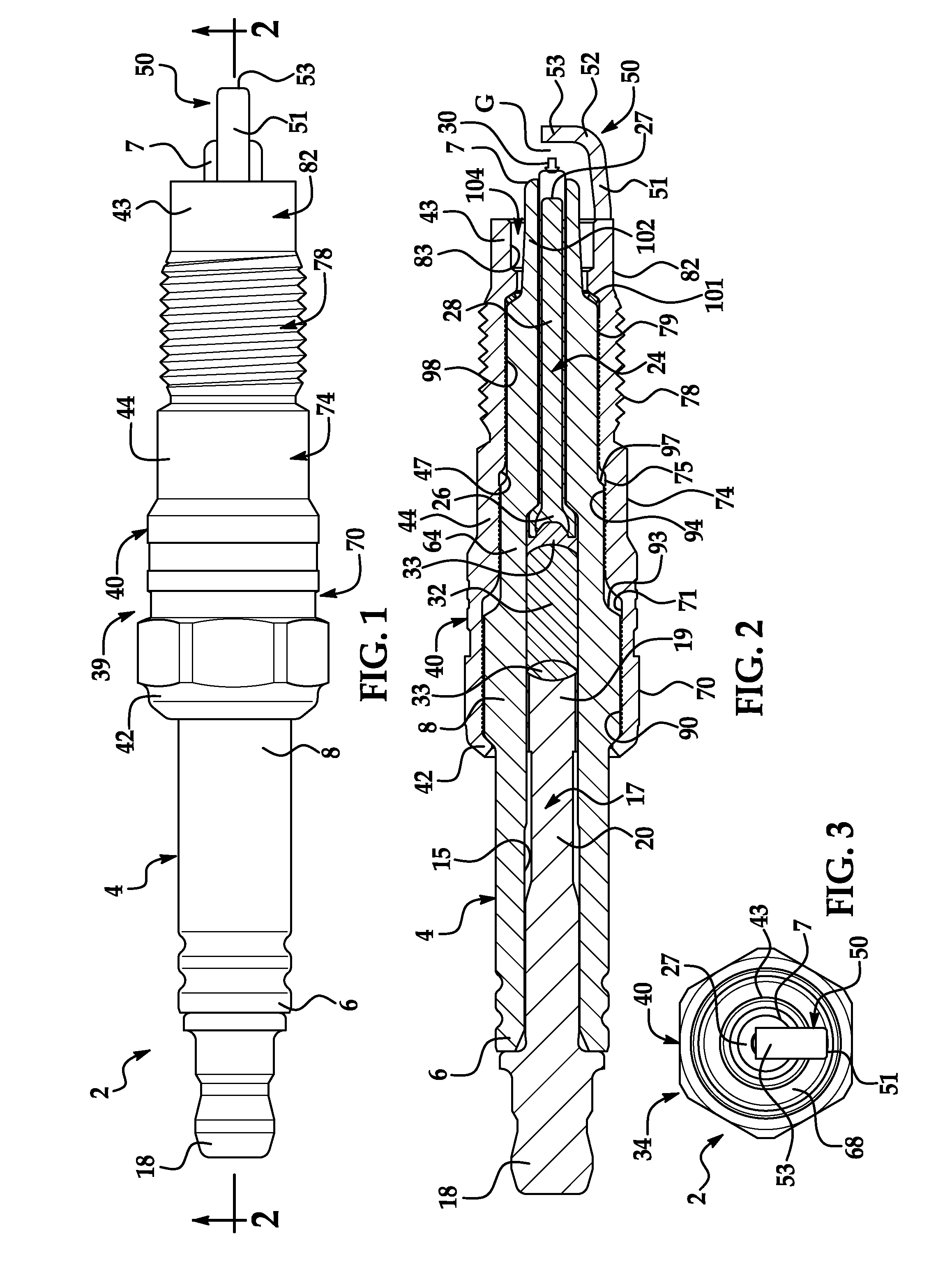
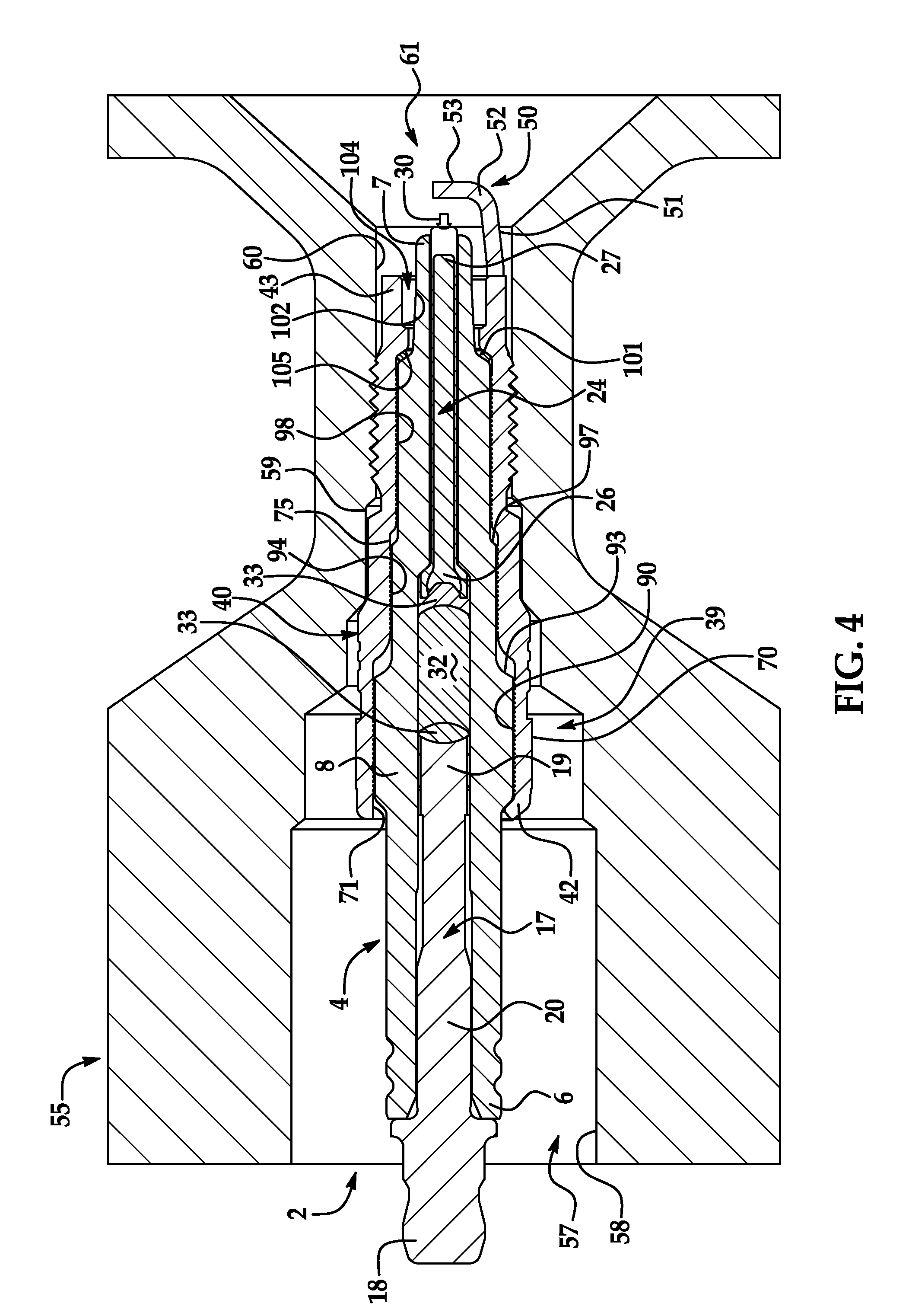
[0012]With initial reference to FIGS. 1-3, a small diameter spark plug constructed in accordance with an exemplary embodiment of the present invention is indicated generally at 2. Spark plug 2 includes an electrically insulating sleeve or insulator 4 having a first end portion 6, a second end portion 7 and an intermediate portion 8. Insulator 4 includes an axial bore 15 that extends between first and second end portions 6 and 7.

[0013]As shown in FIG. 2, spark plug 2 includes a first electrode 17 arranged in an upper portion (not separately labeled) of axial bore 15. First electrode 17 includes a first end or tip section 18 that extends out beyond first end portion 6 of insulator 4 and a second end section 19. The first end section 18 and the second end section 19 are joined together through the intermediate section 20. Spark plug 2 also includes a second electrode or center wire 24 arranged in a lower portion (not separately labeled) of axial bore 15. Second electrode 24 includes a ...


PUM


Abstract

A small diameter spark plug configuration is provided, the configuration has been found to provide additional volume for the insulator member. That is, by limiting the overall number of threads on the intermediate portion along with a limit of the overall diameter of the spark plug, additional volume of insulator material may be achieved in an interior cavity of a metal shell of the spark plug. This additional volume enables a portion of the insulator member to have a larger diameter and hence greater material thickness. The larger diameter of the insulator provides enhanced dielectric properties and protects internal components of the spark plug from high combustion chamber temperatures while simultaneously providing a robust attachment of the spark plug with an engine head.

Description

CROSS REFERENCE TO RELATED APPLICATION[0001]This application claims the benefit of the following U.S. Provisional Patent application Ser. No. 61 / 024,045 filed Jan. 28, 2008, the contents of which are incorporated herein by reference thereto.FIELD OF THE INVENTION[0002]Exemplary embodiments of the present invention relate to spark plugs and, more particularly, to a small diameter spark plug having an enhanced insulator.BACKGROUND OF THE INVENTION[0003]In general, spark plugs include an insulating sleeve having a central axial bore through which a center electrode extends. The insulating sleeve is positioned within and secured to a metal shell that serves as a mounting platform / interface to an internal combustion engine. The metal sleeve also supports a ground electrode that is positioned in a particular spaced relationship relative to the central electrode so as to define a spark gap. The spark plug is typically mounted to an engine cylinder head and selectively activated to deliver ...

Claims


Application Information

Patent Timeline
IPC IPC(8): H01T13/20
CPCH01T13/32H01T13/20
Inventor BELOW, MATTHEW B.
Owner BMO HARRIS BANK N A AS SUCCESSOR COLLATERAL AGENT
Why Eureka
Try Eureka