Touch panel device and user interface device

a technology of user interface and touch panel, which is applied in the direction of electric digital data processing, instruments, computing, etc., can solve the problem of not being able to realize a user interface devi

Inactive Publication Date: 2009-07-30
MITSUBISHI ELECTRIC CORP
View PDF15 Cites 91 Cited by
  • Summary
  • Abstract
  • Description
  • Claims
  • Application Information

AI Technical Summary

Benefits of technology

[0010]According to the present invention, a decision is made as to whether two points are touched or not on the touch panel according to the resistance values between the opposite terminals, the touch panel having resistive films which have electrode terminals at opposite end portions each and are superimposed top and bottom in such a manner that the electrode terminals become orthogonal, the top and bottom resistive films being brought into contact with eac

Problems solved by technology

The conventional analog touch panel device, however, has a problem of being unable to realize a user interface device th

Method used


Image

  • Touch panel device and user interface device
  • Touch panel device and user interface device
  • Touch panel device and user interface device

Examples


embodiment 1

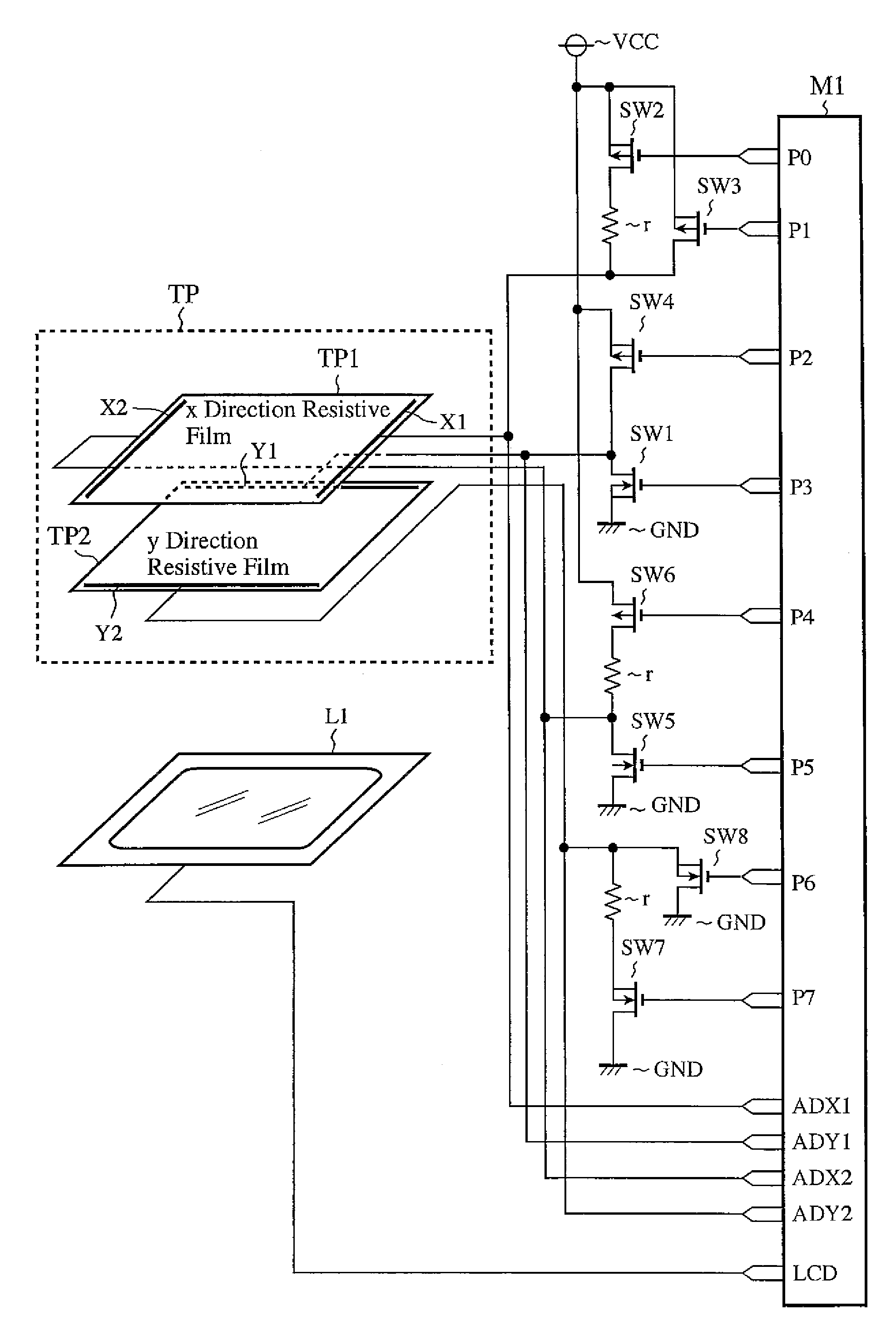
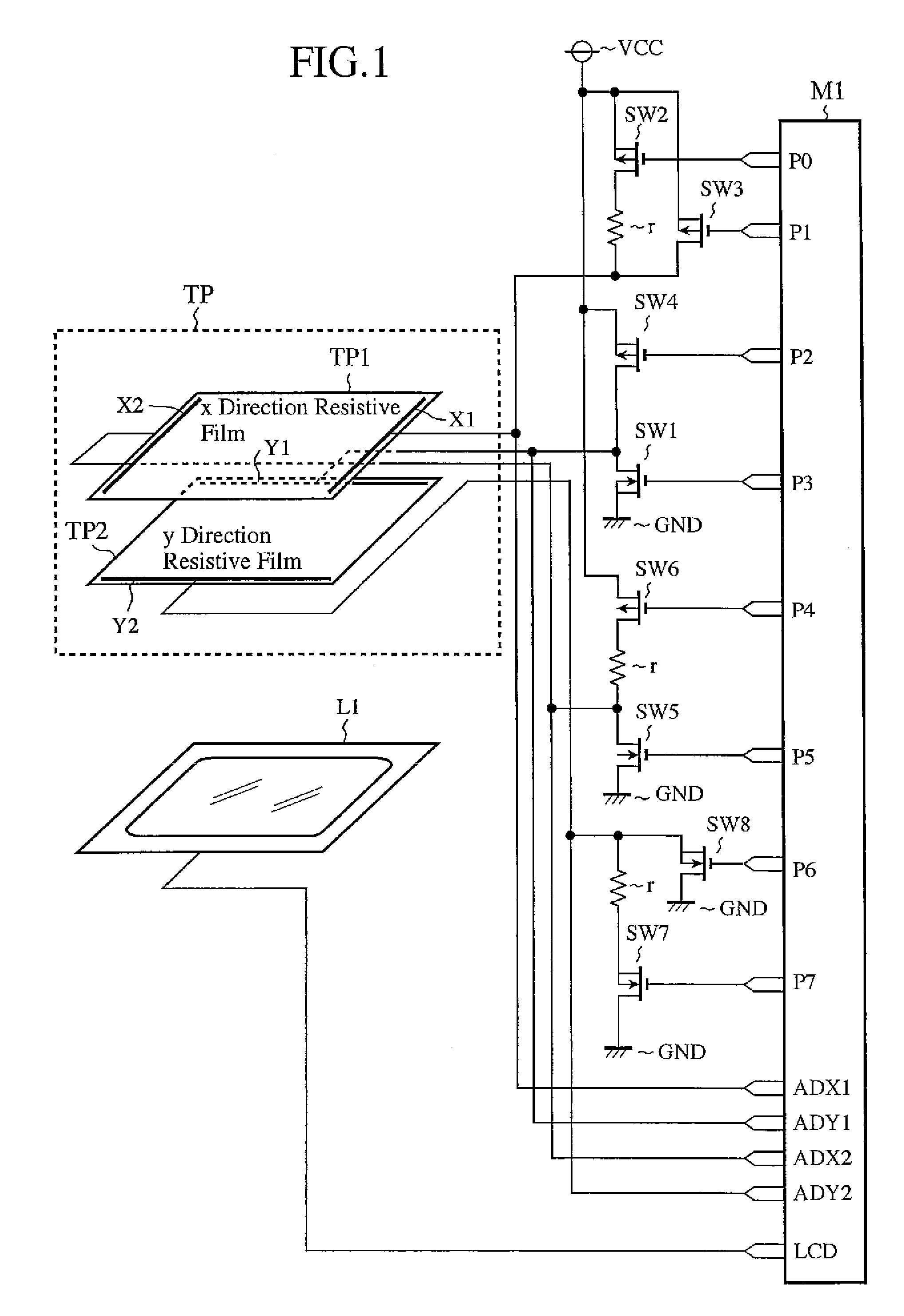
[0035]FIG. 1 is a circuit diagram showing a configuration of a touch panel device of an embodiment 1 in accordance with the present invention. In FIG. 1, a touch panel TP has two analog resistive films TP1 and TP2. The resistive film TP1 (referred to as “x direction resistive film TP1” from now on) has terminals (electrode terminals) X1 and X2 which consist of a pair of electrodes provided at both edges in the x direction. Likewise, the resistive film TP2 (referred to as “y direction resistive film TP2” from now on) has terminals (electrode terminals) Y1 and Y2 which consist of a pair of electrodes provided at both edges in the y direction (direction perpendicular to the X direction). Thus, the touch panel TP has the two resistive films TP1 and TP2 superimposed in such a manner that the terminals X1 and X2 and terminals Y1 and Y2 become orthogonal.

[0036]A microcontroller M1 is a component for detecting a touch position on the touch panel TP and for causing an LCD unit L1 to display ...

embodiment 2

[0068]The foregoing embodiment 1 is described by way of example of the touch panel device that makes a decision as to whether two points are touched or not using the reduction in the resistance values between opposite terminals measured at the touch on the panel, and detects, when a decision is made that the two points are touched, the distance between the two points from the resistance values between the opposite terminals in the x direction and y direction.

[0069]As for the method of making a decision as to whether two points are touched or not using the reduction in the resistance values between opposite terminals, however, it is conceivable that the decision accuracy as to whether two points are touched or not deteriorates when the distance between the two points touched on the panel reduces (in the case of R4→0 in FIG. 8(b)) because it approaches the state in which one point is touched as shown in FIG. 7.

[0070]Accordingly, the present embodiment 2 makes a decision as to whether ...

embodiment 3

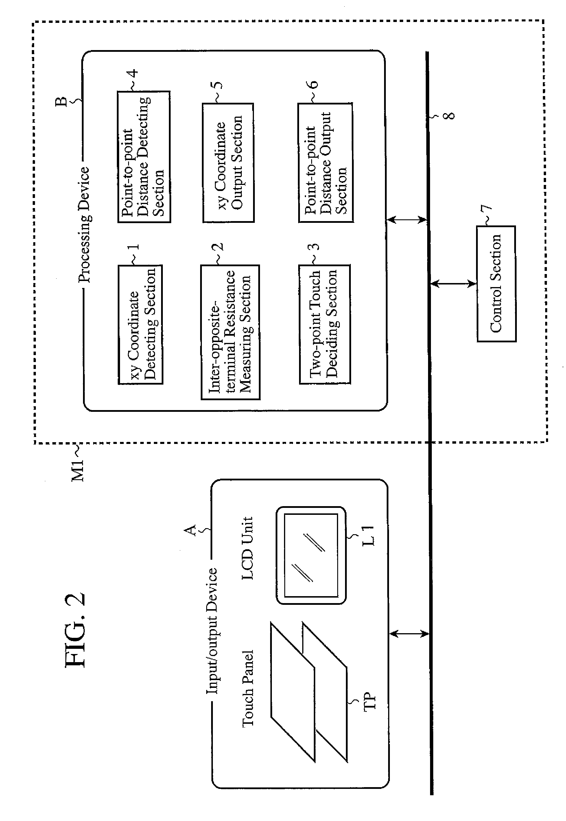
[0090]The foregoing embodiments 1 and 2 are described by way of example of the touch panel device that decides as to whether two points are touched or not using the resistance values between the opposite terminals or between the orthogonal terminals, and detects the distance between the two points from the resistance values between the opposite terminals on the panel. The present embodiment 3, in addition to the touch panel device described in the foregoing embodiment 1 or 2, has the function of outputting, when the decision of the two-point touch is made, the information on the distance between the two points the point-to-point distance detecting section 4 detects from the resistance values between the opposite terminals, and the xy coordinates near the middle point between the touched points the xy coordinate detecting section 1 detects.

[0091]Although the touch panel device of the present embodiment 3 has basically the same configuration as that of the foregoing embodiment 1 or 2,...


PUM


Abstract

An analog touch panel device capable of utilizing a two-point touch on a touch panel as meaningful information input and a user interface device employing the analog touch panel device are provided. A decision is made as to whether two points are touched or not on a touch panel TP having resistive films which have electrode terminals at opposite end portions each and are superimposed top and bottom in such a manner that the electrode terminals become orthogonal, in which the top and bottom resistive films are brought into contact with each other by a push of a resistive film surface by touch input. The decision is made according to resistance values between the opposite terminals, and when a decision is made that the two points are touched, the distance between the two points touched is detected according to the resistance values between the opposite terminals.

Description

BACKGROUND OF THE INVENTION[0001]1. Field of the Invention[0002]The present invention relates to a touch panel device and a user interface device using it.[0003]2. Description of Related Art[0004]As a touch panel device for deciding touching on a plurality of points on a touch panel, there is one disclosed in Patent Document 1, for example. The device of Patent Document 1 utilizes a phenomenon that when a plurality of points are touched on the touch panel, a resistance value between opposite terminals on a two-layer touch panel reduces. To be concrete, to prevent a malfunction due to touching on a plurality of points on the touch panel, it makes a decision that the plurality of points are touched only when the resistance value between the opposite terminals of the touch panel measured varies greater than a reference value.[0005]Patent Document 1: Japanese Patent Laid-Open No. 8-241161 / 1996SUMMARY OF THE INVENTION[0006]The analog touch panel device utilizing the resistance values bet...

Claims


Application Information

Patent Timeline
IPC IPC(8): G06F3/045G06F3/0488
CPCG06F3/045G06F2203/04808G06F3/04883G06F3/0412G06F3/0416G06F1/1601
Inventor WASHINO, HIROYUKIOKANO, YUICHIKAWAMATA, TAKENORI
Owner MITSUBISHI ELECTRIC CORP
Why Eureka
Try Eureka