
Optical code division multiplexing transmission and reception method and optical code division multiplexing transceiver

a transceiver and optical code technology, applied in the field of optical transceivers, can solve the problems of increasing the number of parts, reducing the signal to noise ratio (snr) of the played back optical pulse signal constituting the reception signal, and reducing the communication speed and larger capacity of metro areas. the effect of reducing the intensity of the optical pulse signal playback signal

Inactive Publication Date: 2009-07-30
OKI ELECTRIC IND CO LTD
View PDF8 Cites 4 Cited by
  • Summary
  • Abstract
  • Description
  • Claims
  • Application Information

AI Technical Summary

Benefits of technology

[0046]Therefore, an object of the present invention is to provide an OCDM transceiver that is capable of solving the problem that the intensity of the correlation waveform signal decreases and the problem that the number of parts constituting the receiver increases.
[0054]Therefore, the insertion loss that is produced as a result of using the optical branching filter in the decoding step that includes the time gate processing step is not produced. That is, if the OCDM transceiver of the present invention is used, the decrease in intensity of the optical pulse signal playback signal (correlation waveform signal) caused by separating the clock signal extraction signal from the playback optical pulse signal can be reduced below that of conventional devices of the same type. As a result, the problem with the decrease in the S / N ratio of the played back optical pulse signal constituting the reception signal can be solved.
[0055]Further, because the optical branching filter that is required by conventional devices of the same type is no longer required, the number of parts including auxiliary parts required for installation of an optical branching filter can be reduced. Therefore, the problem that the number of parts constituting the decoding portion increases can be resolved.

Problems solved by technology

Although bit rates of Internet backbones have already been secured up to Terabit communication bandwidths, higher communication speeds and larger capacities for metro areas have fallen behind.
As a result, there is the problem that the signal to noise ratio (SNR) of the played back optical pulse signal constituting the reception signal decreases.
There is also the problem that of the increase in the number of parts constituting the receiver on the reception side that comprises the decoding function.

Method used


Image

  • Optical code division multiplexing transmission and reception method and optical code division multiplexing transceiver
  • Optical code division multiplexing transmission and reception method and optical code division multiplexing transceiver
  • Optical code division multiplexing transmission and reception method and optical code division multiplexing transceiver

Examples


Embodiment Construction

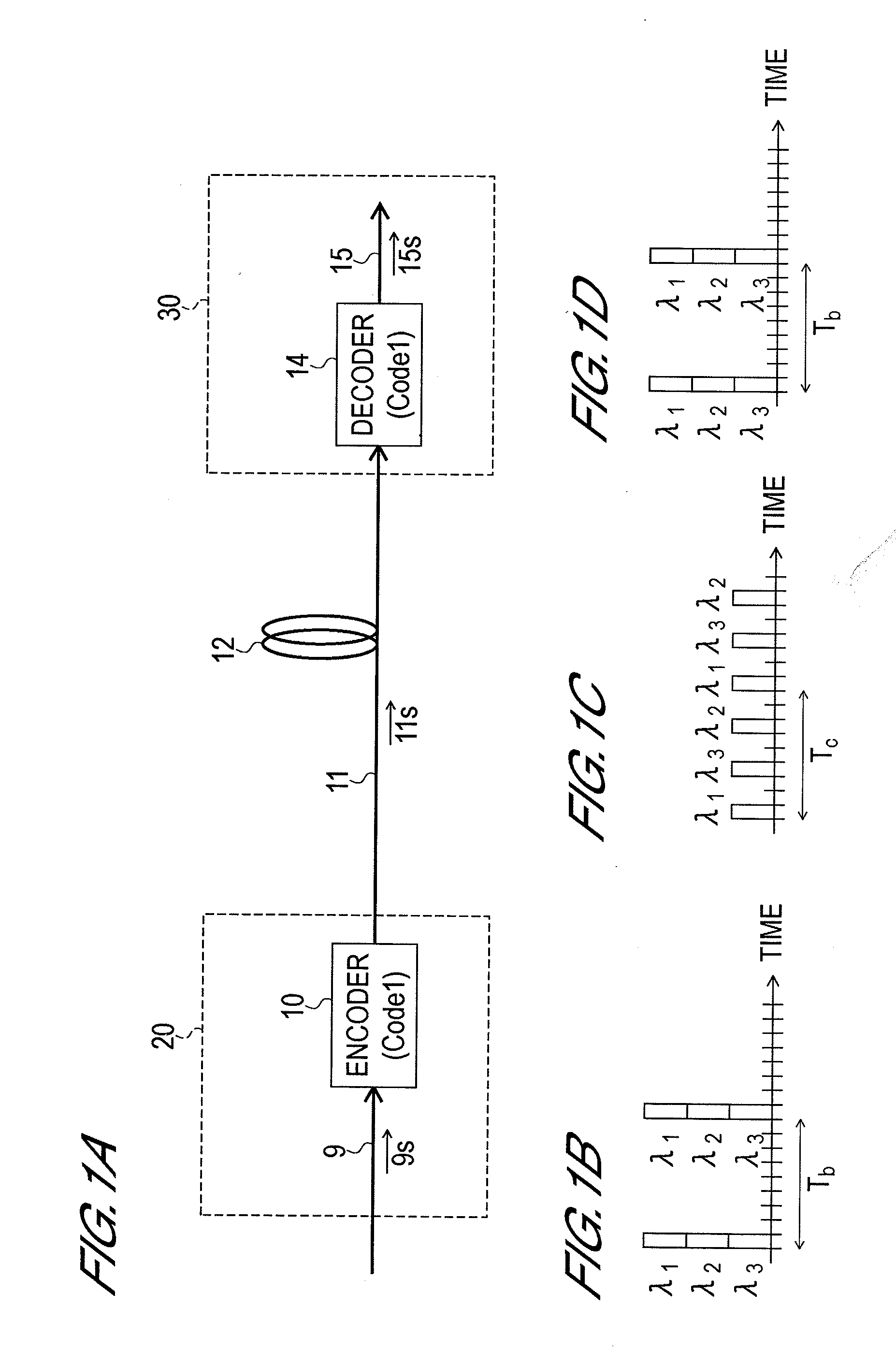
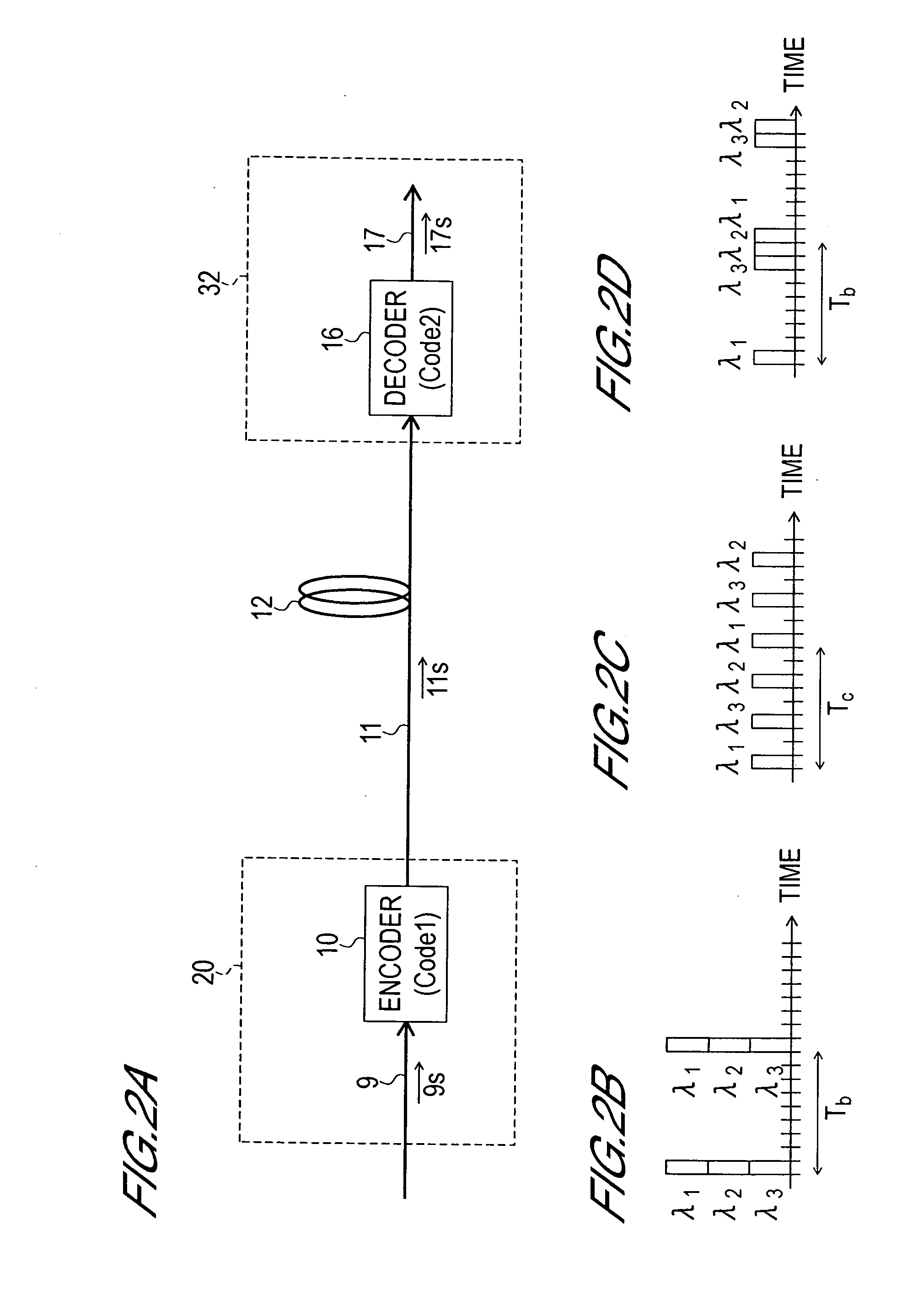
[0067]Embodiments of the present invention will be described hereinbelow with reference to the drawings. Further, each figure only shows a constitutional example of the present invention and only schematically shows the cross-sectional shape and dispositional relationship and so forth of each constituent element to the extent of permitting an understanding of the present invention. The present invention is not limited to the illustrated examples. Further, although specified materials and conditions and so forth are sometimes employed in the following description, these materials and conditions constitute only one of the suitable examples and the present invention is therefore in no way limited to or by such materials and conditions and so forth. Further, the same numbers are sometimes shown appended to the same constituent elements in each of the drawings and repeated descriptions are sometimes avoided.

[0068]In the drawings shown hereinbelow, the path of an optical pulse signal in a...


PUM


Abstract

An object of the present invention is to provide an OCDM transceiver with which the reduction amount of the intensity of the correlation waveform signal is smaller than that of a conventional device of the same type in the decoding step that comprises a time gate processing step. Hence, in the OCDM transceiver of the present invention that comprises an encoding portion and a decoding portion, the decoding portion is constituted comprising a decoder, clock extractor, and time gate. The decoder decodes an encoded optical pulse signal and separates the encoded optical pulse signal into a clock signal extraction signal and an optical pulse signal playback signal. The clock extractor extracts a clock signal from the clock signal extraction signal. Further, the time gate removes only the auto-correlation waveform component from the optical pulse signal playback signal. The auto-correlation waveform component is converted to an electrical signal by means of an optical receiver and generated as a reception signal.

Description

CROSS-REFERENCE TO RELATED PATENT APPLICATION[0001]This application is a continuation of U.S. patent application Ser. No. 11 / 284,971, filed Nov. 23, 2005, the subject matter of which application is incorporated herein by reference in its entirety.[0002]This application claims the benefit of Japanese Patent Application No. 2004-341616, filed on Nov. 26, 2004, in the Japanese Property Office, the disclosure of which is incorporated herein in its entirety by reference.BACKGROUND OF THE INVENTION[0003]1. Field of the Invention[0004]The present invention relates to an optical transceiver and, more particularly, to encoding and clock signal extraction means for an optical code division multiplexing (OCDM) transceiver.[0005]2. Description of Related Art[0006]Metro-areas that are located between long-distance networks (also known as an ‘Internet backbone’) and access lines necessitate higher communication speeds and increased capacities. Although bit rates of Internet backbones have already...

Claims


Application Information

Patent Timeline
Patent Type & Authority Applications(United States)
IPC IPC(8): H04J14/00H04B1/713H04B10/524H04B10/572H04J14/04H04J14/06
CPCH04J14/005H04J14/02
Inventor MINATO, NAOKINISHIKI, AKIHIKO
Owner OKI ELECTRIC IND CO LTD
Learn More