Electric-powered pump

a technology of electric power and pump, which is applied in the direction of positive displacement liquid engine, piston pump, liquid fuel engine, etc., can solve the problems of increasing the size of the entire fuel supply apparatus, and time-consuming manufacturing of the fuel supply apparatus and the fuel pressure adjustment apparatus, so as to achieve easy manufacturing and reduce size and cost

Active Publication Date: 2017-03-21
MITSUBISHI ELECTRIC CORP
View PDF8 Cites 0 Cited by
  • Summary
  • Abstract
  • Description
  • Claims
  • Application Information

AI Technical Summary

Benefits of technology

[0007]However, in conventional fuel supplying apparatuses, because it is necessary to secure space for installing the fuel pressure adjusting apparatus inside the cylinder block, the cylinder block is increased in size, increasing the entire fuel supplying apparatus in size. Furthermore, because the fuel pressure adjusting apparatus is installed inside the cylinder block separately, the number of parts in the fuel pressure adjusting apparatus is also increased, not only preventing cost reductions, but also making manufacturing of the fuel supplying apparatus and the fuel pressure adjusting apparatus time-consuming.
[0008]The present invention aims to solve the above problems and an object of the present invention is to provide an electric-powered pump that can be easily manufactured, and that enables size reductions and cost reductions to be achieved.
[0010]An electric-powered pump according to the present invention can be easily manufactured, and reductions in size and cost can be achieved.

Problems solved by technology

However, in conventional fuel supplying apparatuses, because it is necessary to secure space for installing the fuel pressure adjusting apparatus inside the cylinder block, the cylinder block is increased in size, increasing the entire fuel supplying apparatus in size.
Furthermore, because the fuel pressure adjusting apparatus is installed inside the cylinder block separately, the number of parts in the fuel pressure adjusting apparatus is also increased, not only preventing cost reductions, but also making manufacturing of the fuel supplying apparatus and the fuel pressure adjusting apparatus time-consuming.

Method used


Image

  • Electric-powered pump
  • Electric-powered pump
  • Electric-powered pump

Examples


embodiment 1

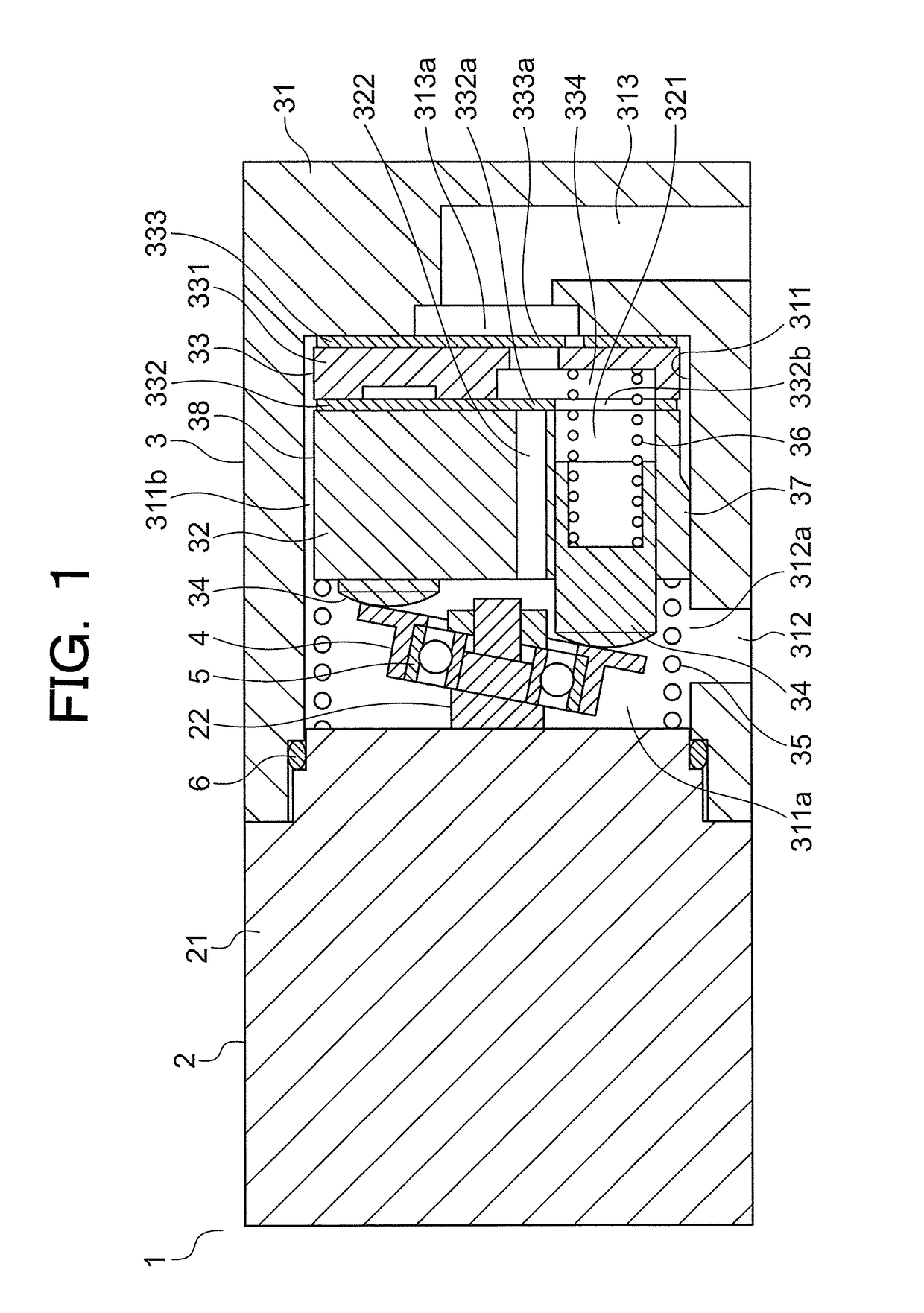
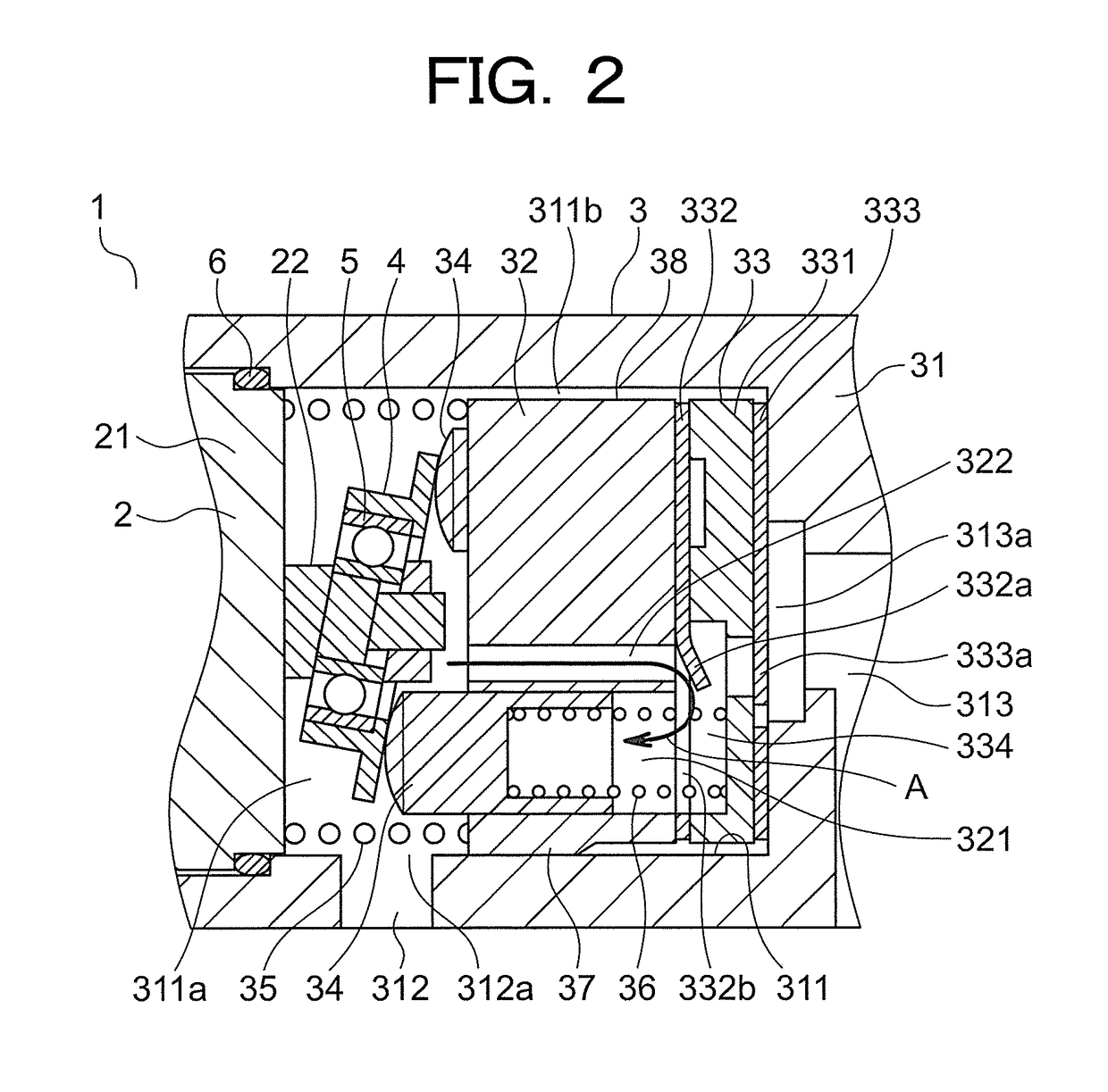
[0024]FIG. 1 is a cross section that shows an electric-powered pump according to Embodiment 1 of the present invention. In the figure, an electric-powered pump 1 has: a motor portion 2; a pump portion 3 that is disposed on the motor portion 2, and that is operated by a driving force from the motor portion 2; and a driver portion (not shown) that is mounted onto the motor portion 2, and that controls the motor portion 2. In this example, the electric-powered pump 1 is an automotive electric-powered oil pump that is mounted to a vehicle such as an automobile. Furthermore, in this example, the electric-powered pump is used in an idling reduction system as an oil pump that fills a transmission with oil (a hydraulic pump that generates pressure inside the transmission) during idling reduction in order to reduce departure shock immediately after an engine is restarted.

[0025]The motor portion 2 has: a motor portion main body 21; and a rotating shaft 22 that protrudes from the motor portion...

embodiment 2

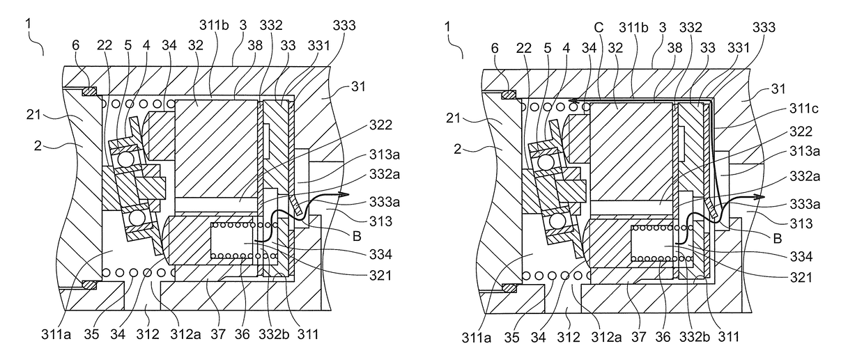
[0054]FIG. 5 is a cross section that shows an electric-powered pump according to Embodiment 2 of the present invention. A movable body 38 further includes: a fixing plate 301 that is stacked on a valve apparatus 33; and a rod-shaped interfitting pin 303 that is fixed to a fixing plate 301, that passes through a valve apparatus 33, and that is fitted into a cylinder 32. The fixing plate 301 and the interfitting pin 303 are movable through an accommodating chamber 311 together with the cylinder 32 and the valve apparatus 33. A gap 311b exists between the movable body 38, including the fixing plate 301, and a side surface of the accommodating chamber 311.

[0055]The fixing plate 301 is stacked on a discharging valve 333 so as to be disposed between the valve apparatus 33 and a discharging orifice 313a. A plate penetrating aperture 302 that passes through the fixing plate 301 is disposed on the fixing plate 301. The fixing plate 301 is stacked on the discharging valve 333 such that the po...

embodiment 3

[0063]FIG. 9 is a cross section that shows an electric-powered pump according to Embodiment 3 of the present invention. A movable body 38 further includes a case 304 on which is disposed a recess portion 305 into which a cylinder 32 and a valve apparatus 33 are fitted together. The case 304 is movable through an accommodating chamber 311 together with the cylinder 32 and the valve apparatus 33.

[0064]The case 304 has: a cylindrical tubular portion 304a that surrounds outer circumferences of the cylinder 32 and the valve apparatus 33; and a bottom plate portion 304b that is fixed to an end portion of the tubular portion 304a, and that is disposed between the valve apparatus 33 and a discharging orifice 313a. The recess portion 305 is formed by the tubular portion 304a and the bottom plate portion 304b.

[0065]A case penetrating aperture 306 that passes through the bottom plate portion 304b is disposed on the bottom plate portion 304b of the case 304. An interior of the recess portion 3...


PUM


Abstract

A movable body that has a cylinder and a valve apparatus is accommodated inside an accommodating chamber of a pump body so as to cover a discharging orifice. A piston sucks a fluid into the movable body, and discharges the fluid from inside the movable body to the discharging orifice by being slid reciprocally through a piston sliding aperture of the cylinder. A relieving passage that communicates between a suction volume space of the accommodating chamber and the discharging orifice is formed between an inner surface of the accommodating chamber and the movable body by the movable body moving away from the discharging orifice in opposition to a force from a forcing body.

Description

BACKGROUND OF THE INVENTION[0001]1. Field of the Invention[0002]The present invention relates to an electric-powered pump that performs suction and discharging of a fluid by a driving force from a motor portion.[0003]2. Description of the Related Art[0004]In recent years, as fuel economy of automobiles, etc., has improved and exhaust emissions regulations have tightened, adoption of idling reduction systems has advanced as a technique that that can be expected to be highly effective in improving fuel economy and reducing emissions comparatively simply and conveniently. Idling reduction systems are systems that stop an engine during temporary stopping or during low-speed movement of an automobile and restart the engine when starting to move again. Electric-powered pumps have been used in idling reduction systems in order to generate pressure inside a transmission or to fill the transmission with oil during idling reduction in order to reduce departure shock immediately after the engi...

Claims


Application Information

Patent Timeline
Patent Type & Authority Patents(United States)
IPC IPC(8): F04B1/18F04B1/14F04B53/10F04B7/02
CPCF04B1/18F04B1/141F04B1/143F04B1/146F04B53/1037F04B7/02
Inventor NOSE, SHINYASOGA, HIDEHIROAOTA, MASAYUKI
Owner MITSUBISHI ELECTRIC CORP
Why Eureka
Try Eureka