Electric-powered pump
a technology of electric power and pump, which is applied in the direction of positive displacement liquid engine, piston pump, liquid fuel engine, etc., can solve the problems of increasing the size of the entire fuel supply apparatus, and time-consuming manufacturing of the fuel supply apparatus and the fuel pressure adjustment apparatus, so as to achieve easy manufacturing and reduce size and cost
- Summary
- Abstract
- Description
- Claims
- Application Information
AI Technical Summary
Benefits of technology
Problems solved by technology
Method used
Image
Examples
embodiment 1
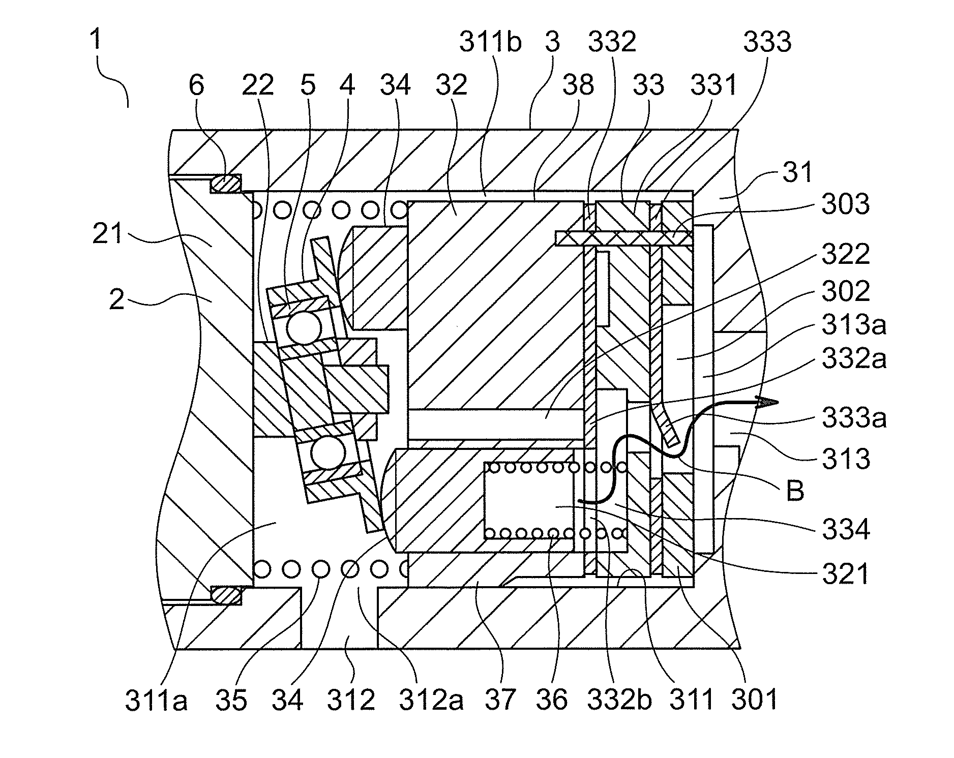
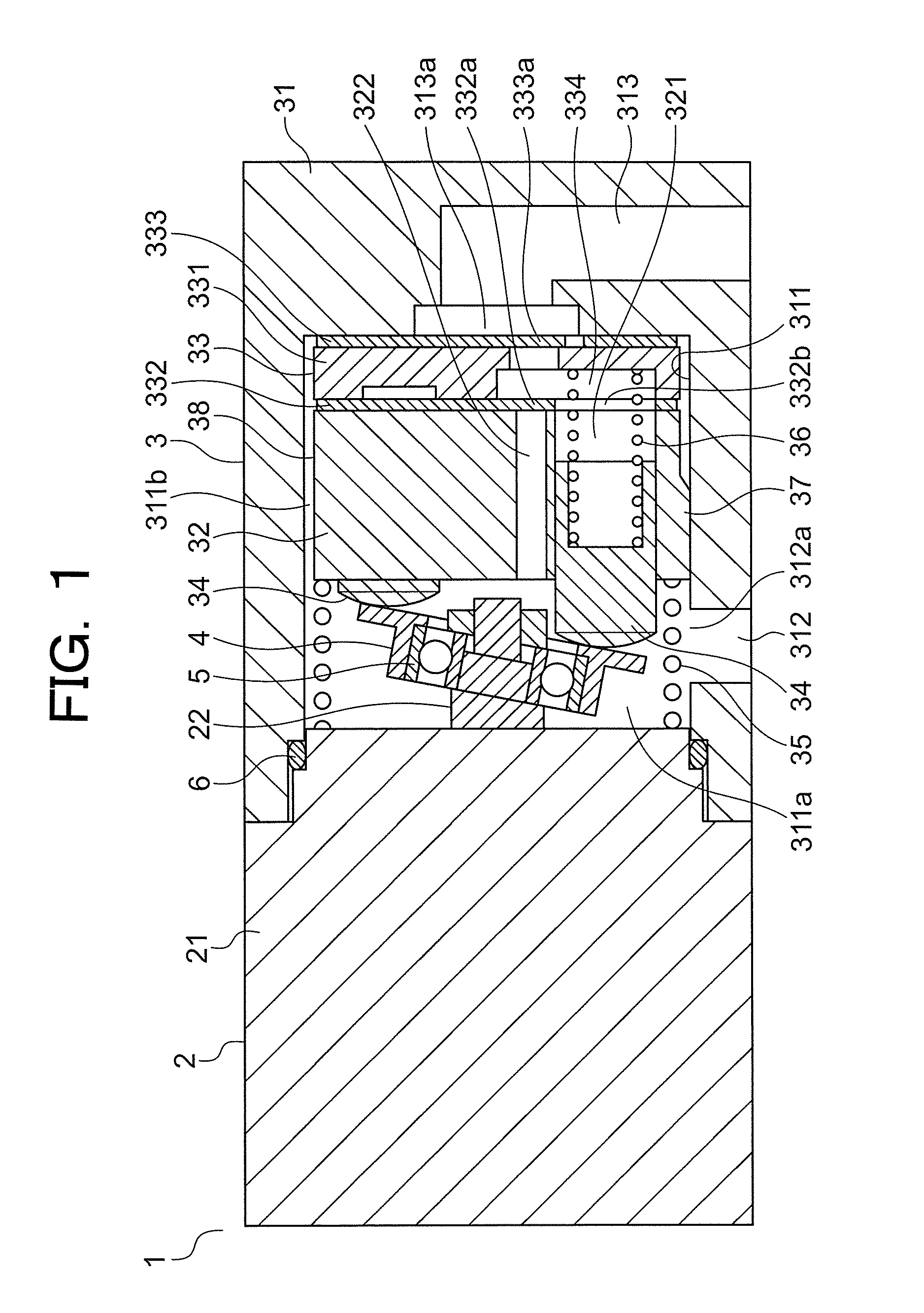
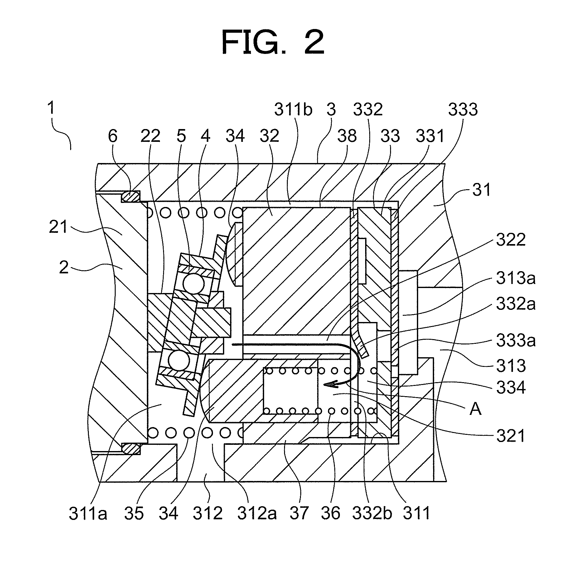
[0024]FIG. 1 is a cross section that shows an electric-powered pump according to Embodiment 1 of the present invention. In the figure, an electric-powered pump 1 has: a motor portion 2; a pump portion 3 that is disposed on the motor portion 2, and that is operated by a driving force from the motor portion 2; and a driver portion (not shown) that is mounted onto the motor portion 2, and that controls the motor portion 2. In this example, the electric-powered pump 1 is an automotive electric-powered oil pump that is mounted to a vehicle such as an automobile. Furthermore, in this example, the electric-powered pump is used in an idling reduction system as an oil pump that fills a transmission with oil (a hydraulic pump that generates pressure inside the transmission) during idling reduction in order to reduce departure shock immediately after an engine is restarted.
[0025]The motor portion 2 has: a motor portion main body 21; and a rotating shaft 22 that protrudes from the motor portion...
embodiment 2
[0054]FIG. 5 is a cross section that shows an electric-powered pump according to Embodiment 2 of the present invention. A movable body 38 further includes: a fixing plate 301 that is stacked on a valve apparatus 33; and a rod-shaped interfitting pin 303 that is fixed to a fixing plate 301, that passes through a valve apparatus 33, and that is fitted into a cylinder 32. The fixing plate 301 and the interfitting pin 303 are movable through an accommodating chamber 311 together with the cylinder 32 and the valve apparatus 33. A gap 311b exists between the movable body 38, including the fixing plate 301, and a side surface of the accommodating chamber 311.
[0055]The fixing plate 301 is stacked on a discharging valve 333 so as to be disposed between the valve apparatus 33 and a discharging orifice 313a. A plate penetrating aperture 302 that passes through the fixing plate 301 is disposed on the fixing plate 301. The fixing plate 301 is stacked on the discharging valve 333 such that the po...
embodiment 3
[0063]FIG. 9 is a cross section that shows an electric-powered pump according to Embodiment 3 of the present invention. A movable body 38 further includes a case 304 on which is disposed a recess portion 305 into which a cylinder 32 and a valve apparatus 33 are fitted together. The case 304 is movable through an accommodating chamber 311 together with the cylinder 32 and the valve apparatus 33.
[0064]The case 304 has: a cylindrical tubular portion 304a that surrounds outer circumferences of the cylinder 32 and the valve apparatus 33; and a bottom plate portion 304b that is fixed to an end portion of the tubular portion 304a, and that is disposed between the valve apparatus 33 and a discharging orifice 313a. The recess portion 305 is formed by the tubular portion 304a and the bottom plate portion 304b.
[0065]A case penetrating aperture 306 that passes through the bottom plate portion 304b is disposed on the bottom plate portion 304b of the case 304. An interior of the recess portion 3...
PUM
 Abstract
Description
Claims
Application Information
 - R&D
- Intellectual Property
- Life Sciences
- Materials
- Tech Scout
- Unparalleled Data Quality
- Higher Quality Content
- 60% Fewer Hallucinations
Browse by: Latest US Patents, China's latest patents, Technical Efficacy Thesaurus, Application Domain, Technology Topic, Popular Technical Reports.
© 2025 PatSnap. All rights reserved.Legal|Privacy policy|Modern Slavery Act Transparency Statement|Sitemap|About US| Contact US: help@patsnap.com


