Electromechanical brake pressure generator including a gear and method for manufacturing a gear for an electromechanical brake pressure generator

Pending Publication Date: 2022-09-29
ROBERT BOSCH GMBH
View PDF0 Cites 0 Cited by
  • Summary
  • Abstract
  • Description
  • Claims
  • Application Information

AI Technical Summary

Problems solved by technology

For decelerating passenger cars, the foot force of the driver is usually insufficient, so that passenger cars are normally equipped with a brake booster.
Alternative brake pressure build-up devices are required for future drive concepts of motor vehicles, since underpressure is no longer available for ope

Method used


Image

  • Electromechanical brake pressure generator including a gear and method for manufacturing a gear for an electromechanical brake pressure generator
  • Electromechanical brake pressure generator including a gear and method for manufacturing a gear for an electromechanical brake pressure generator
  • Electromechanical brake pressure generator including a gear and method for manufacturing a gear for an electromechanical brake pressure generator

Examples


Embodiment Construction

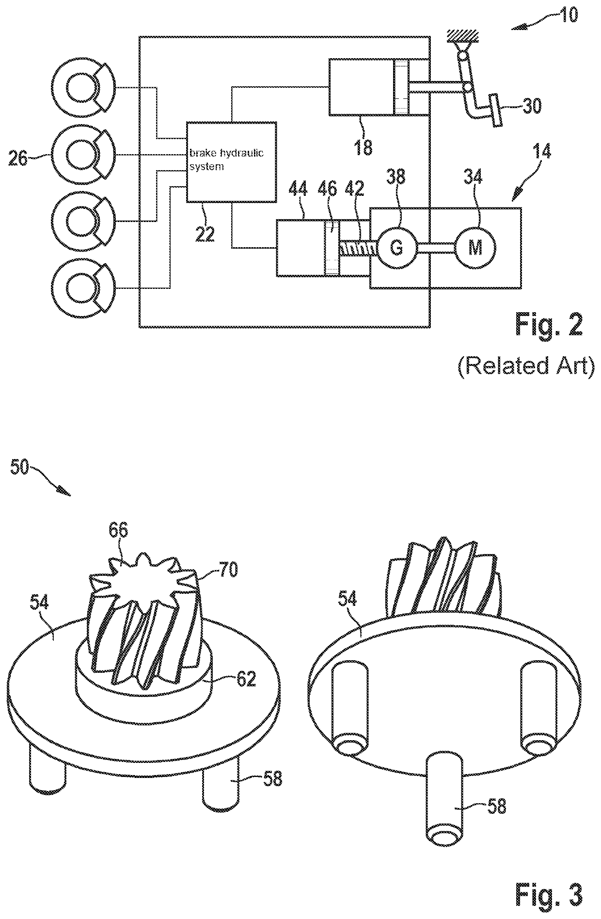
[0030]A simplified schematic representation of a hydraulic braking system 10 from the related art for a vehicle including an electromechanical brake pressure generator 14 is shown in FIG. 2. Hydraulic braking system 10 includes electromechanical brake pressure generator 14 and a piston / cylinder unit 18. Piston / cylinder unit 18 and electromechanical brake pressure generator 14 are both hydraulically connected to a brake hydraulic system 22, which is represented here only as a box.

[0031]Brake hydraulic system 22 is formed by various valves and further components to form a, for example, electronic stability program (ESP). In order to be able to decelerate the vehicle, brake hydraulic system 22 is also connected to at least one wheel braking unit 26, so that by a corresponding switching of valves, a brake force may be applied at wheel brake unit 26.

[0032]Piston / cylinder unit 18 is actuated using muscle force via a brake pedal 30. In contrast, the brake force of electromechanical brake p...


PUM


Abstract

An electromechanical brake pressure generator for a hydraulic braking system of a vehicle. The electromechanical brake booster includes at least one gear for transferring a torque of the electric motor for brake pressure generation. The gear in this case includes a planetary carrier for supporting planetary wheels, planetary wheels pins which are connected to the planetary carrier and on which the planetary wheels are rotatably fastenable, and a pinion for transferring a drive torque or output torque, which is rotatably fixedly connected to the planetary carrier at a side thereof opposite the planetary wheel pins. At least the part of the planetary carrier that includes the planetary wheel pins is materially integrally formed with the latter from the same material.

Description

FIELD[0001]The present invention relates to an electromechanical brake pressure generator including a gear, a method for manufacturing a gear of an electromechanical brake pressure generator, and a vehicle including an electromechanical brake pressure generator.[0002]The electromechanical brake pressure generator in this case may also be used as a brake booster, in which an input brake force is boosted. The electromechanical brake pressure generator or brake booster includes, in particular, a gear for transferring a torque of the electric motor for brake pressure generation. For the sake of simplicity, reference is made below solely to a brake pressure generator.BACKGROUND INFORMATION[0003]For decelerating passenger cars, the foot force of the driver is usually insufficient, so that passenger cars are normally equipped with a brake booster. In general, brake boosters frequently operate with an underpressure generated by an internal combustion engine. The pressure difference between ...

Claims


Application Information

Patent Timeline
IPC IPC(8): B60T13/74B60T13/68
CPCB60T13/745B60T13/686B60T13/746B60Y2200/91
Inventor OEHLER, CHRISTOPHOEHLER, CLAUSBOEHM, MARKUHLIG, MARTINREICHERT, SEBASTIAN MARTIN
Owner ROBERT BOSCH GMBH
Why Eureka
Try Eureka