
Bulb Socket Structure for Onboard Interior Lighting System

a technology for interior lighting and bulb sockets, which is applied in the direction of coupling device details, electrical discharge lamps, coupling device connections, etc., can solve the problems of bulb sockets being loose and shaky in holding pieces, power supply terminals being accordingly deformed, and abnormal nois

Inactive Publication Date: 2009-07-30
YAZAKI CORP
View PDF5 Cites 6 Cited by
  • Summary
  • Abstract
  • Description
  • Claims
  • Application Information

AI Technical Summary

Benefits of technology

[0011]The present invention has been made with the foregoing conditions taken into consideration. For this reason, an object of the present invention is to provide a bulb socket structure for an onboard interior lighting system which allows a bulb to be attached to its power supply terminals smoothly with no power supply terminals being deformed inadvertently, as well as which is capable of preventing the bulb from being in a wrong contact with the power supply terminal, and from causing abnormal noises, due to its loose and shaky contact condition.

Problems solved by technology

In the case of the bulb socket structures described in each patent document, it is likely that the base of the bulb may collide against the power supply terminals in the bulb attachment hole when the wedge base bulb is inserted into the bulb attachment hole, and that the power supply terminals may be accordingly deformed.
As a result, the bulb tends to be loose and shaky in the holding pieces thereof.
Once the bulb becomes loose and shaky in the holding pieces thereof, the bulb contacts the power supply terminals 110 in a wrong condition, and the shake of the bulb causes abnormal noises.
These are problems with the conventional model of bulb socket structure.

Method used


Image

  • Bulb Socket Structure for Onboard Interior Lighting System
  • Bulb Socket Structure for Onboard Interior Lighting System
  • Bulb Socket Structure for Onboard Interior Lighting System

Examples


Embodiment Construction

[0038]Descriptions will be provided hereinbelow for the embodiment of the present invention by referring to FIGS. 3 to 9.

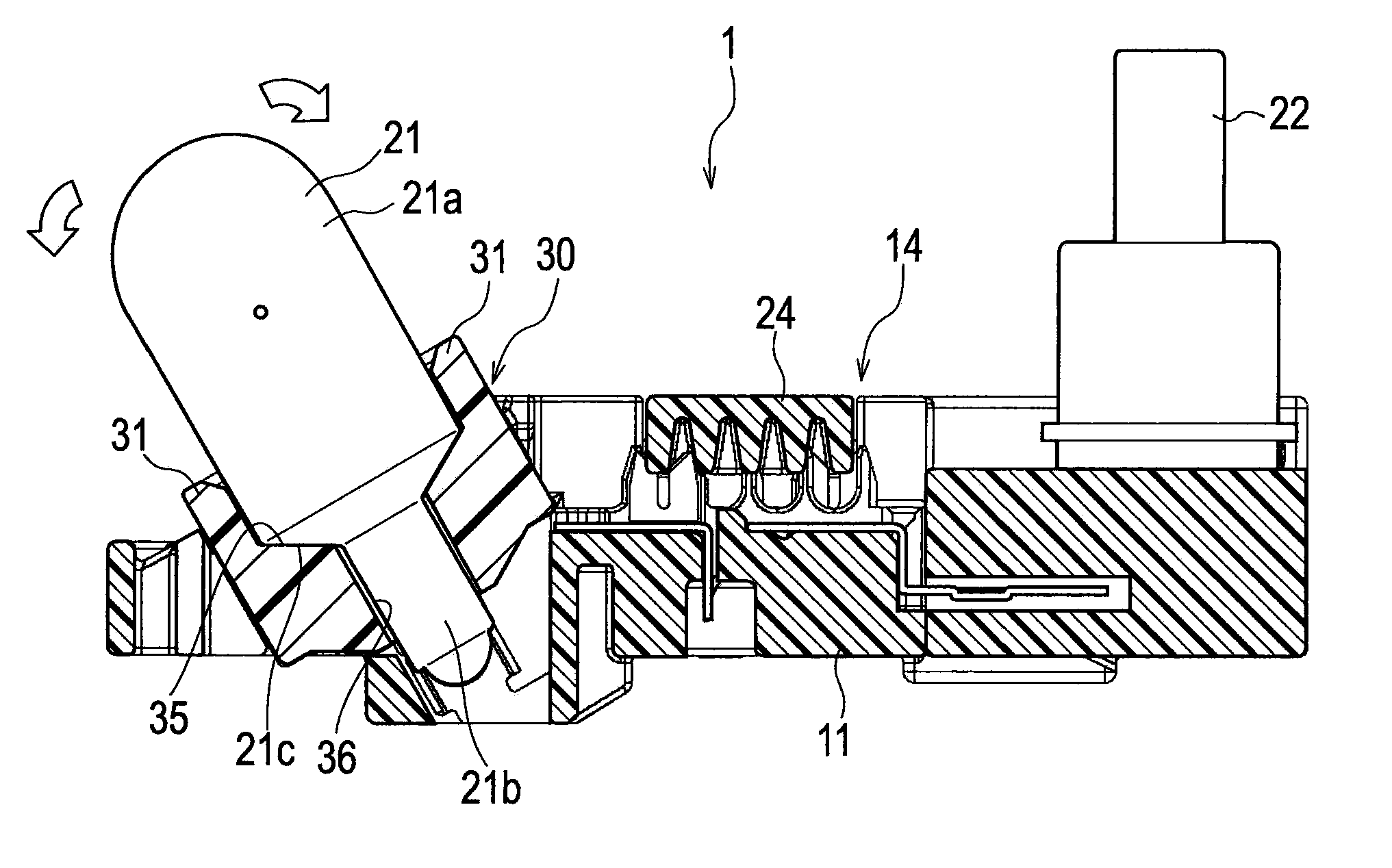
[0039]First of all, an onboard interior lighting system, to which a bulb socket structure according to the embodiment is applied, includes a functional section 1. The functional section 1 shown in FIG. 3 is provided to an exterior side of a ceiling board (a rear side of the ceiling) of a vehicle. This functional section 1 includes: a resin-made housing 10 serving as a functional section main body; a wedge base bulb 21 (hereinafter simply referred to as a “bulb”) and a switch 22; an electric wire protecting cover 24. The housing 10 includes: an electric wire connector 14 to which the wires are connected; a bulb attachment (a bulb attachment hole 12) to which the bulb 21 as a light source is attached; and a switch attachment 13 to which the switch 22 is attached. The switch 22 is that with which to select one among modes of conducting electricity to the bulb 21. The...


PUM


Abstract

Disclosed is a bulb socket structure for an onboard interior lighting system, in which: a bulb attachment hole 12 to which a wedge base bulb 21 is attached is formed in a resin-made housing 10 constituting the onboard interior lighting system; and power supply terminals 15 configured to contact, and conduct electricity to, terminals of a base 21b arranged under a bulb part 21a of the wedge base bulb when the base is inserted into the inside of the bulb attachment hole are provided in the inside of the bulb attachment hole. In the bulb socket structure, a spacer 30 is provided to the bulb attachment hole 12. The spacer is includes a supporting cylindrical part 31 capable of supporting the bulb part 21a of the wedge base bulb from its outer periphery. The spacer is capable of causing the power supply terminals 15 to contact the respective terminals of the base part while protecting the power supply terminals. Guiding slopes 35 configured to guide the base 21b to a right position in the inside of the bulb attachment hole 12 while the base is being inserted to the bulb attachment hole are provided to the inside of the supporting cylindrical part.

Description

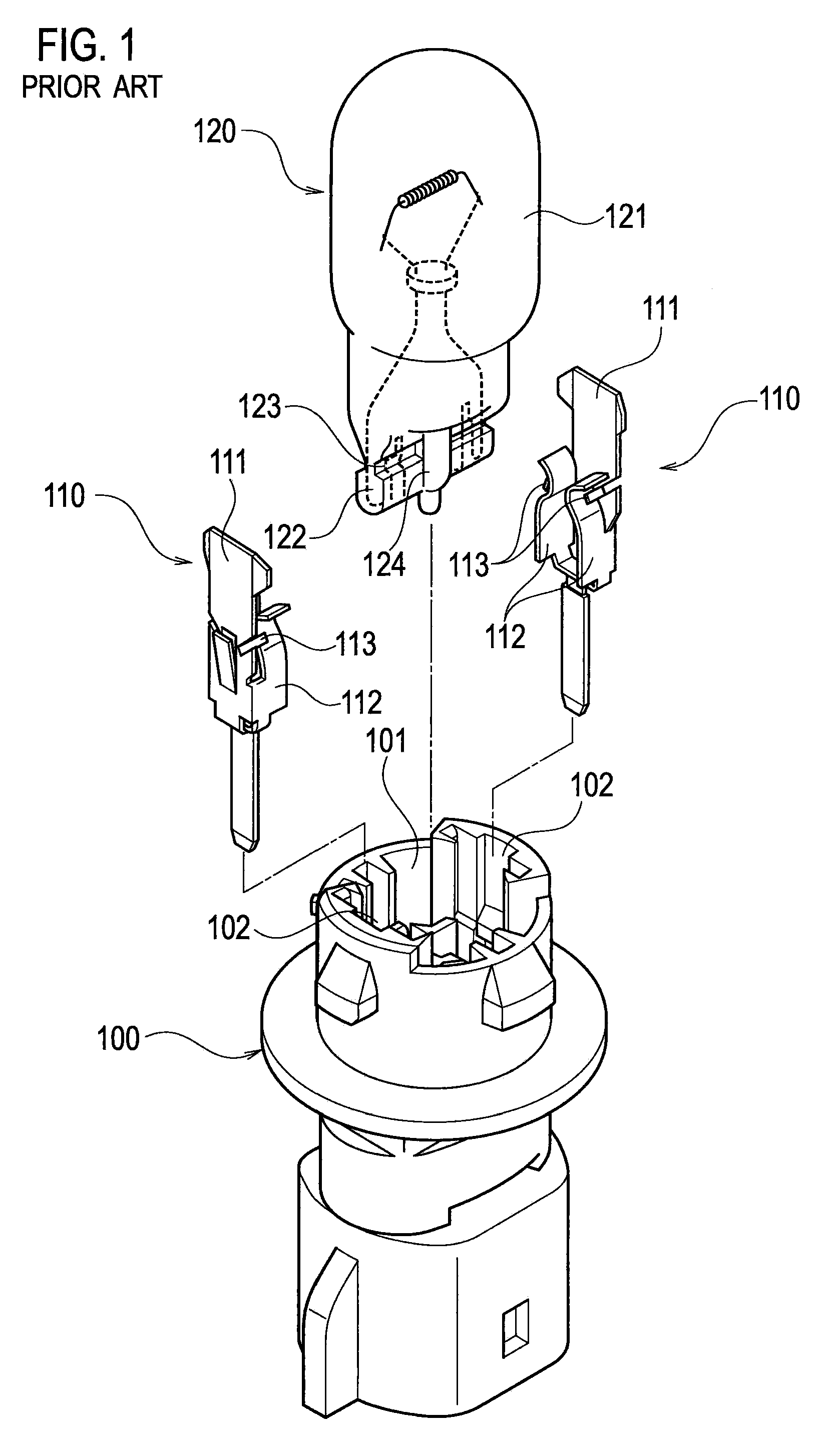
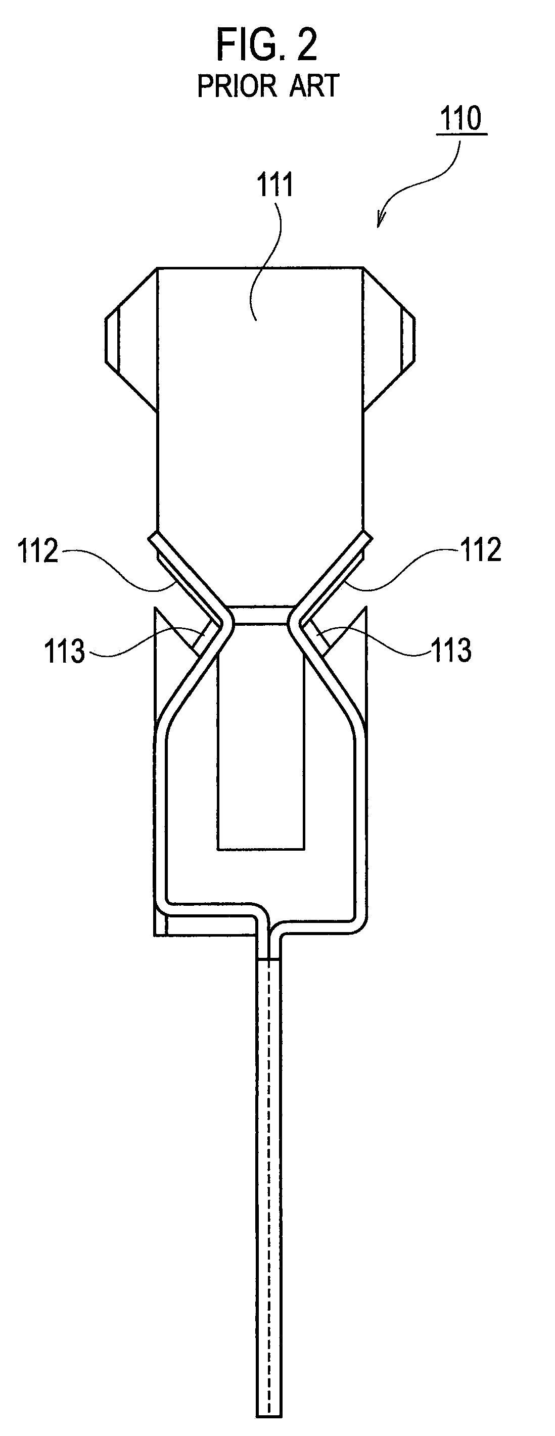
BACKGROUND OF THE INVENTION[0001]1. Field of the Invention[0002]The present invention relates to a bulb socket structure for an onboard interior lighting system provided to a ceiling of a vehicle.[0003]2. Description of the Related Art[0004]FIG. 1 is an exploded, perspective view showing a conventional model of bulb socket structure disclosed in Japanese Patent Application Laid-Open No. Hei. 7-254466 (Patent Document 1). FIG. 2 is a front view of a chief section of the conventional model of bulb socket structure. This conventional model of bulb socket structure is of a type to which a wedge base bulb 120 is attached. This model of bulb socket structure includes: a resin-made socket main body 100 (equivalent to a housing); and paired power supply terminals 110, 110 fixed to the inside of a bulb attachment hole 101 of the socket main body 100. This bulb socket structure enables a base 122 of the wedge base bulb 120 to be attached to the paired power supply terminals 110, 110.[0005]Eac...

Claims


Application Information

Patent Timeline
IPC IPC(8): H01R24/00
CPCH01R33/09
Inventor NAGAI, KENTAROSUZUKI, YASUOOCHIAI, RYOHEI
Owner YAZAKI CORP
Learn More