Electrode addressing method

Inactive Publication Date: 2009-07-30
COMMISSARIAT A LENERGIE ATOMIQUE ET AUX ENERGIES ALTERNATIVES
View PDF13 Cites 272 Cited by
  • Summary
  • Abstract
  • Description
  • Claims
  • Application Information

AI Technical Summary

Problems solved by technology

For a large number of lines (N=20, 50, 100, etc.), the large number of conductors and relays makes this technology complex and very expensive.
Therefore, we have the prob

Method used


Image

  • Electrode addressing method
  • Electrode addressing method
  • Electrode addressing method

Examples


Embodiment Construction

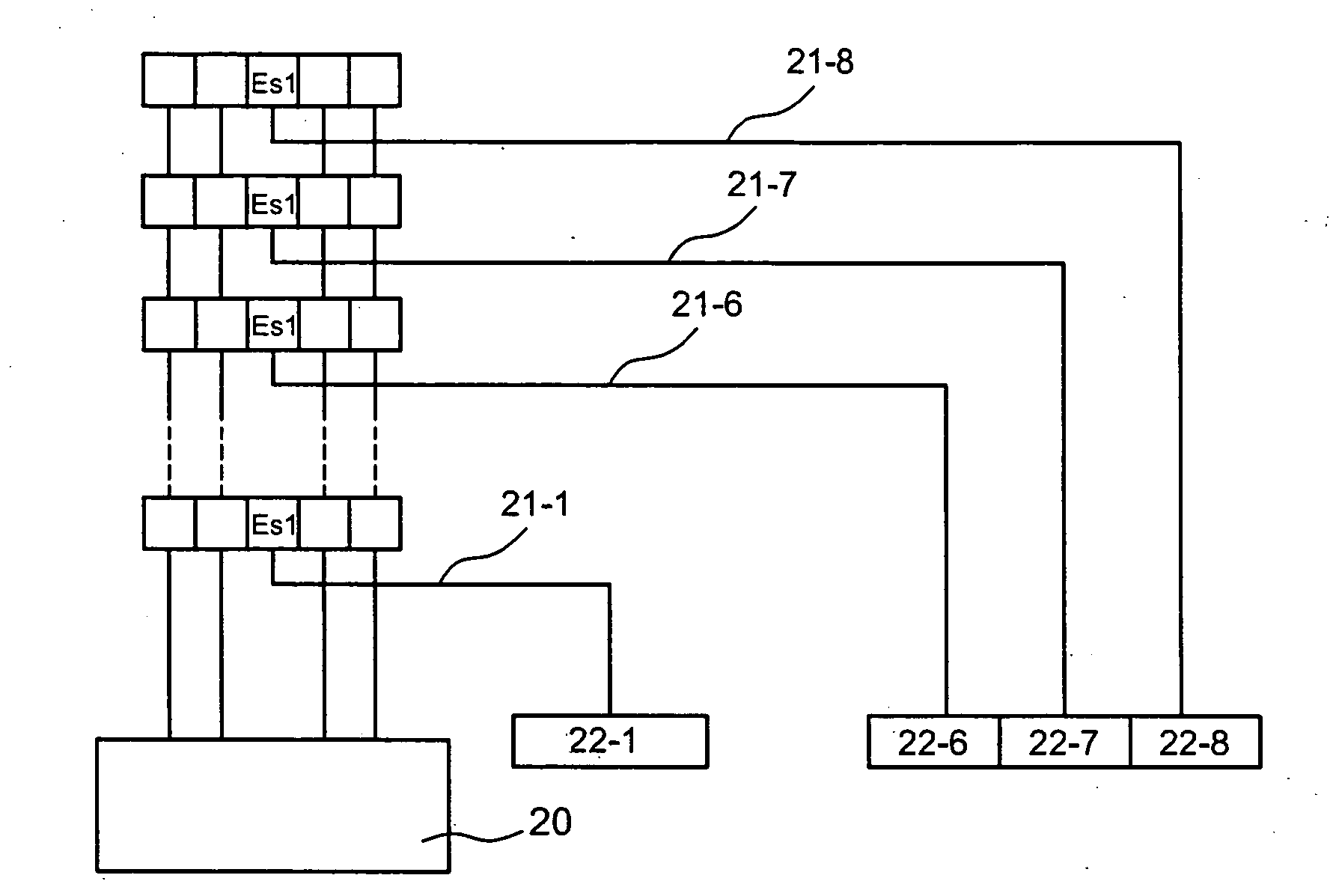
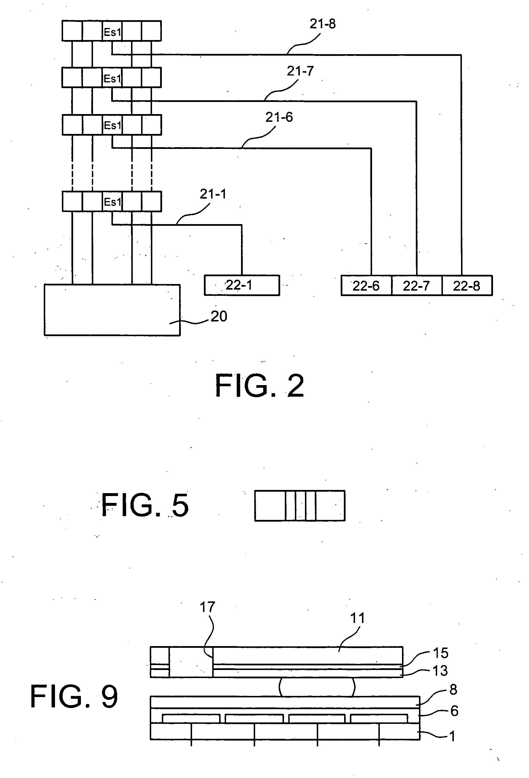
[0036]The invention first relates to a device for addressing an electrode array of 2n lines of an electro-fluidic device, each line having N electrodes (n≦N), which device comprises:[0037]on each line, n so-called selection electrodes, all of these line selection electrodes being connected to 2n line selection conductors, 2n−1 line selection electrodes of 2n−1 lines being connected to each line selection conductor,[0038]selection means, for selecting one or more line selection conductors.

[0039]The invention makes it possible to reduce the number of line selection conductors, and therefore to simplify the line selection means in an electro-fluidic addressing array.

[0040]Owing to the invention, it is therefore possible to manipulate 2n drops for only 2n input signals.

[0041]The invention therefore makes it possible to control line selection electrodes with only 2n relays.

[0042]For example, the invention makes it possible to control 8, 16, 32, 64, 128, 256, 512, 1024 line selection elec...


PUM


Abstract

A device for addressing an electrode array of 2n lines of an electro-fluidic device, each line having N electrodes (n≦N). The device includes, on each line, n selection electrodes, all of the line selection electrodes being connected to 2n line selection conductors, 2n−1 line selection electrodes of 2n−1 lines being connected to each line selection conductor, and selection devices for selecting one or more line selection conductors.

Description

TECHNICAL FIELD AND PRIOR ART[0001]The invention relates to electro-fluidic multiplexing for the manipulation of a plurality of drops in a microsystem.[0002]The invention is particularly suitable for the lab-on-a-chip requiring the testing of a large number of different liquids, for example, for high-rate analysis or combinatorial chemistry.[0003]The reaction volumes are drops manipulated by electrowetting on electrode series.[0004]One of the most commonly used methods of movements or manipulation is based on the principle of electrowetting on a dielectric, as described in the article by M. G. Pollack, A. D. Shendorov, R. B. Fair, entitled “Electro-wetting-based actuation of droplets for integrated microfluidics”, Lab Chip 2 (1) (2002) 96-101.[0005]The forces used for the movement are electrostatic forces.[0006]Document FR 2 841 063 describes a device implementing a catenary opposite electrodes activated for the movement.[0007]The principle of this type of movement is shown in FIGS....

Claims


Application Information

Patent Timeline
IPC IPC(8): C40B30/00C40B60/12
CPCB01F13/0071F04B19/006B01L2300/089B01F13/0076B01F33/3021B01F33/3031
Inventor FOUILLET, YVES
Owner COMMISSARIAT A LENERGIE ATOMIQUE ET AUX ENERGIES ALTERNATIVES
Why Eureka
Try Eureka