Moisture Drainage Spacer Panel for Building Walls

a technology for building walls and moisture drainage, which is applied in the direction of walls, constructions, building components, etc., can solve the problems of deterioration of the masonry exterior covering, condensation formation along the protective barrier, and reduced drainage paths, so as to avoid condensation and prevent condensation. , the effect of reducing the number of times

Active Publication Date: 2009-08-06
BRENTWOOD INDS
View PDF22 Cites 27 Cited by
  • Summary
  • Abstract
  • Description
  • Claims
  • Application Information

AI Technical Summary

Benefits of technology

[0030]It is yet another advantage of this invention that the perforations will not detrimentally affect the ability of the spacer members to resist compression.
[0031]It is still another advantage of this invention that the perforations can be formed in regular or irregular patterns.
[0032]It is yet another object of this invention to provide a baffle vent for use in manufactured housing, which is durable in construction, inexpensive of manufacture, carefree of maintenance, facile in assemblage, and simple and effective in use.
[0033]These and other objects, features and advantages are accomplished according to the instant invention by providing a spacer panel is incorporated into building walls to drain accumulated moisture from the wall structure. The spacer pane...

Problems solved by technology

This temperature differential can result in the formation of condensation along the protective barrier.
In masonry exteriors, particularly stucco and dryvet coverings, the masonry material can absorb the condensation and cause deterioration of the masonry exterior covering.
This spacer member is intended to provide a drainage path for moisture; however, when the exterior covering material compresses the spacer member, the drainage path is reduced and becomes less effective.
Even masonry coverings can result in the collapse of the spacer member as the attachment of the wire mesh to the building substructure can result in the compression of the spacer member, as can the attachment of siding materials to the building substructure.
Trapping moisture is a particular problem with building walls utilizing a protective barrier material wrapped around the building substructure.
The corrugated shape of the undulating ridges and channels are not resistant to compression when exterior materials are nailed or stapled to the interior building substructure.
This type of drainage wrap material is subject to being plugged with masonry materials as the outer surface of the drainage wrap material is not conducive to mounting a protective barrier to prevent the passage of masonry materials into the drainage material.
As ...

Method used


Image

  • Moisture Drainage Spacer Panel for Building Walls
  • Moisture Drainage Spacer Panel for Building Walls
  • Moisture Drainage Spacer Panel for Building Walls

Examples


first embodiment

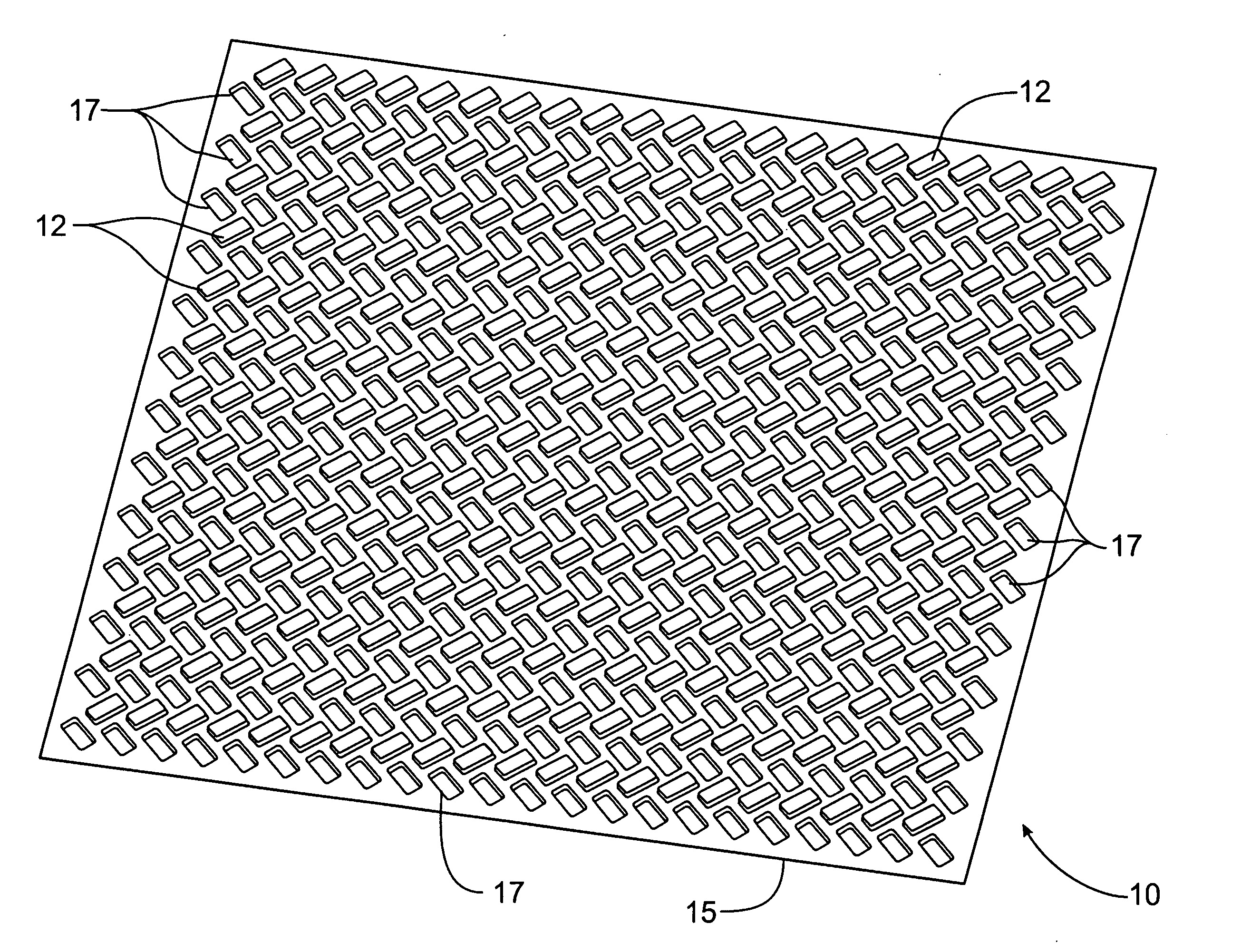
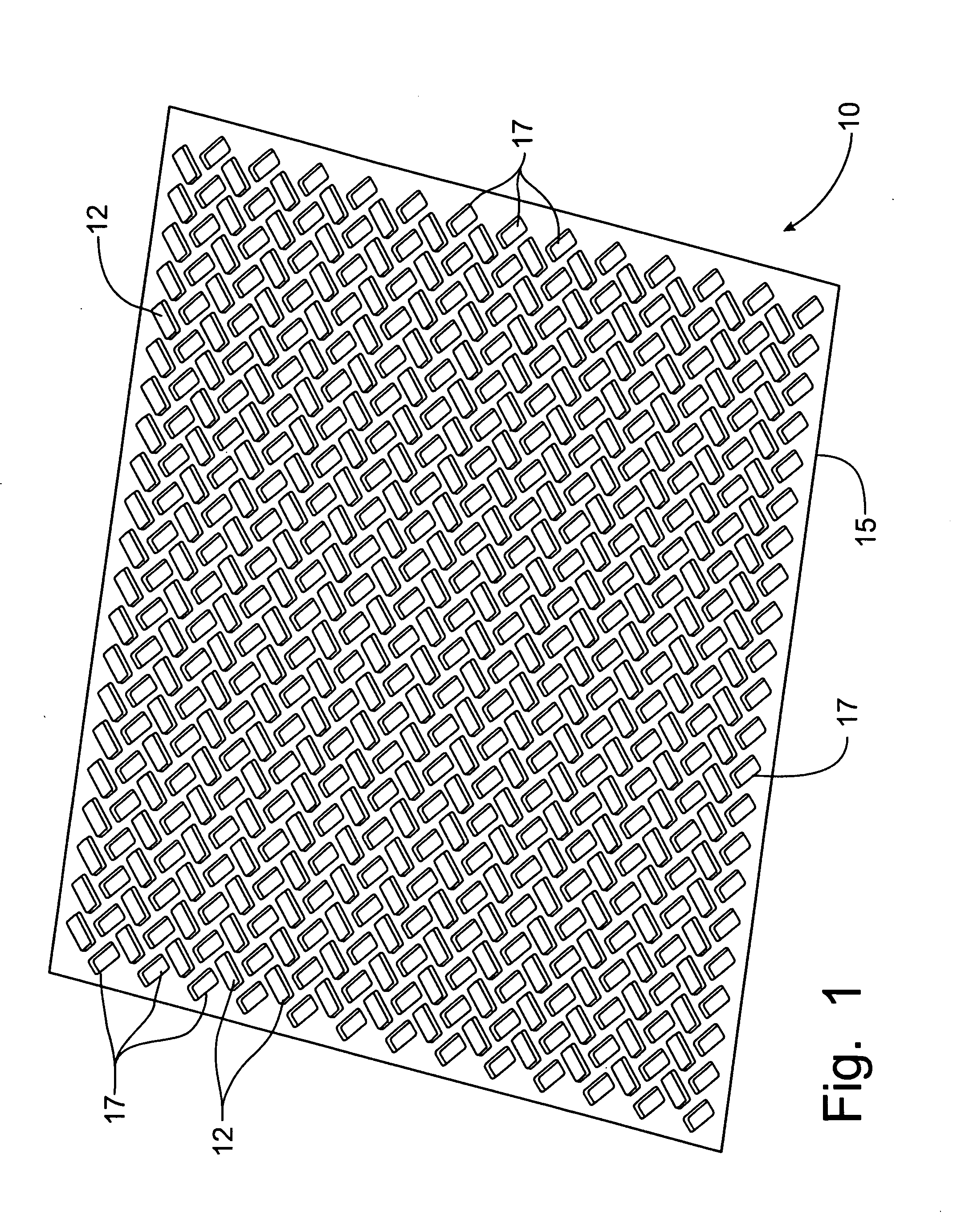
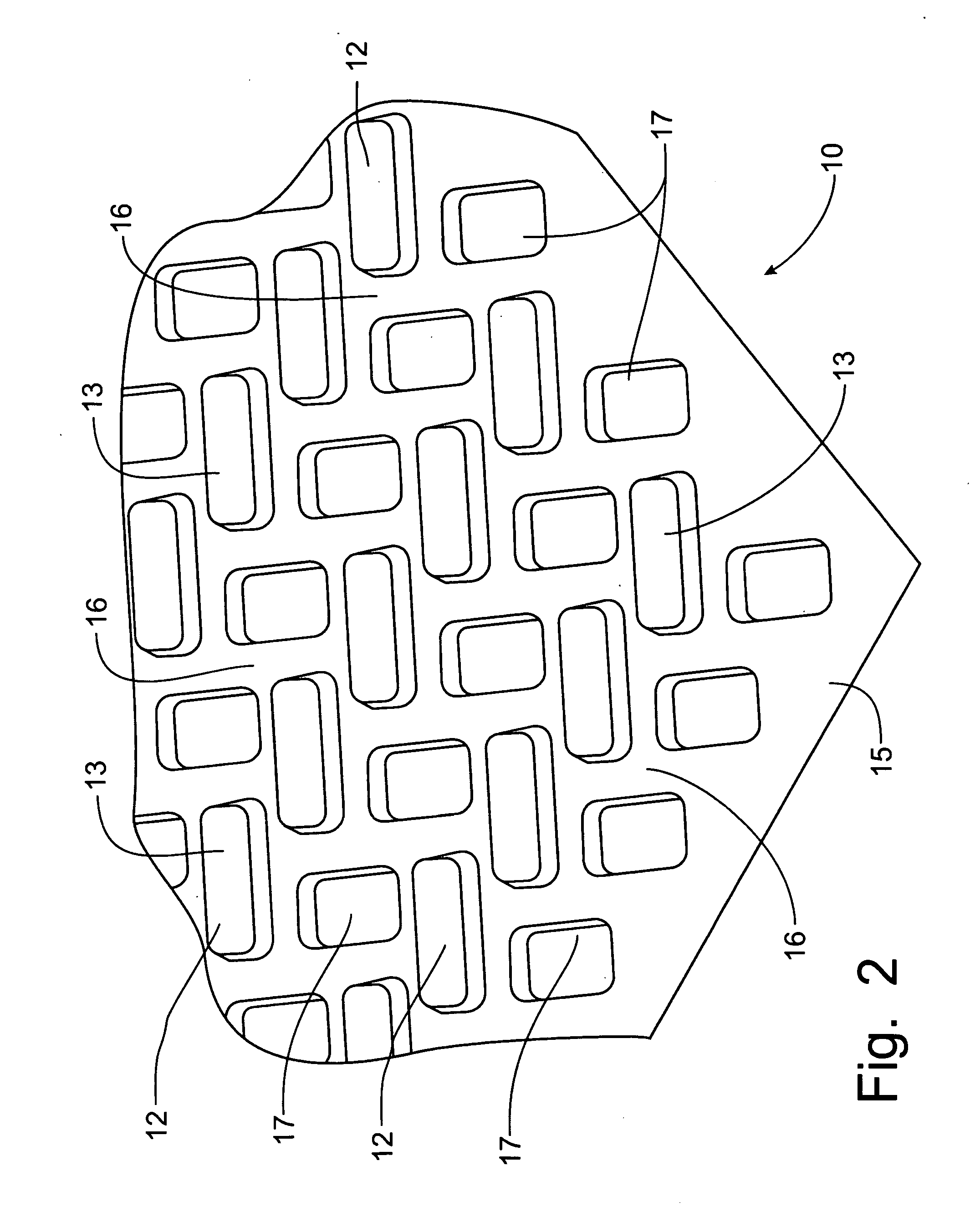
[0046]the spacer panel 10 is formed with a set of first spacer members 12 projecting upwardly from a central panel member 15 and a set of second spacer members 17 extending downwardly from the central panel member 15. The reference to upward and downward are used as a matter of convenience and reflect only that the set of first spacer members 12 project out of the central panel member 15 from one face while the set of second spacer members 17 project out of the central panel member 15 from the opposing face of the panel member 10. As can be seen in FIG. 1, the first and second panel members 12, 17 are arranged in a herringbone pattern that orients the spacer members 12, 17 at approximately forty-five degrees to either major axis of the spacer panel 10.

[0047]Furthermore, with respect to either major axis of the spacer panel 10, the first and second spacer members 12, 17 overlap, which eliminates any open path of the central panel 15 that would extend along either major axis. As a res...

second embodiment

[0056]Looking now at the schematic section of a representative wall construction depicted in FIG. 9, one skilled in the art will note that the spacer panel 10 or 20, the second embodiment being depicted, is placed between the building substructure 30 which is formed of vertical studs 31 supported on a wall plate 32 and having sheathing material 33 fastened with nails or screws, or other fastening devices, to the vertical studs 31 on the outside surface thereof. A protective barrier 34 is wrapped around the sheathing material 33 to stop air and moisture infiltration into the building substructure 30. The spacer panel 20 is then attached to the sheathing material 33 on the outside of the protective barrier 34 by nails, staples or other appropriate fastening devices.

[0057]Preferably, for masonry exterior coverings 35, the spacer panel 20 will have a barrier member 19 attached to the top surfaces 23 of the spacer members 22, preferably through the application of adhesives to bond the ba...


PUM


Abstract

A spacer panel is incorporated into building walls to drain accumulated moisture from the wall structure. The spacer panel is formed with spacer members that project on opposing sides of a central planar web member. Each spacer member is formed independently and has a planar portion extending around the spacer member to provide a location for the insertion of apertures to allow moisture to pass from one side of the panel to the other. Each spacer member includes a planar surface that facilitates an application of adhesive for attachment of a barrier member thereto. The spacer members can be oriented in a herringbone pattern alternating on opposing sides of the central web member. The spacer members can be formed as a circular projection extending on one side of the central web with a truncated conical member projecting to the opposing side of the central web from the circular projection.

Description

CROSS-REFERENCE TO RELATED APPLICATIONS[0001]This application claims priority on U.S. Provisional Patent Application Ser. No. 61 / 026,506, filed Feb. 6, 2008, and entitled “Moisture Drainage Spacer Panel for Building Walls”, the content of which is incorporated herein by reference.FIELD OF THE INVENTION[0002]This invention relates generally to the construction of exterior building walls in a manner to retard deterioration of the wall and the building substructure supporting the wall, and, more particularly, to a plastic film spacer that resists compression while maintaining a drainage path between the exterior building material and the interior building substructure.BACKGROUND OF THE INVENTION[0003]Building walls are constructed with an interior building substructure that is often formed of vertical wood studs and a sheathing material that can be plywood or oriented strand board (OSB), particularly in a residential dwelling, or other known building structural materials, and an exteri...

Claims


Application Information

Patent Timeline
IPC IPC(8): E04B1/70
CPCE04B1/7069E04C2/326E02D31/02E04B2/707
Inventor KORTUEM, MATTROSTEN, DAVID H.RYE, PALLEBONANNI, DAVID J.PIRINO, RICHARD
Owner BRENTWOOD INDS
Why Eureka
Try Eureka