System And Method Of Continuous Detonation In A Gas Turbine Engine

a gas turbine engine and continuous detonation technology, which is applied in the direction of machines/engines, mechanical equipment, lighting and heating apparatus, etc., can solve the problems of reliability problems, valves and associated actuators are subjected to very high temperatures and pressures, and the need for further improvements is becoming increasingly expensive to obtain, etc., to achieve the effect of increasing pressure, increasing pressure and temperature, and increasing pressur

Active Publication Date: 2009-08-06
GENERAL ELECTRIC CO
View PDF29 Cites 23 Cited by
  • Summary
  • Abstract
  • Description
  • Claims
  • Application Information

AI Technical Summary

Problems solved by technology

While engines based on the Brayton Cycle have reached a high level of thermodynamic efficiency by steady improvements in component efficiencies and increases in pressure ratio and peak temperature, further improvements are becoming increasingly costly to obtain.
While such pulse detonation configurations have advanced the state of the art, the valves and associated actuators are subjected to very high temperatures and pressures.
This not only presents a reliability problem, but can also have a detrimental effect on the turbomachinery of the engine.
Other obstacles include the prevention of backflow into the lower pressure regions upstream of the pulse detonator, survivability of turbomachinery and ductwork upstream and downstream of the pulse detonator in an axially unsteady flow field, and capability of cooling flows for maintaining a positive gradient during pulses.

Method used


Image

  • System And Method Of Continuous Detonation In A Gas Turbine Engine
  • System And Method Of Continuous Detonation In A Gas Turbine Engine
  • System And Method Of Continuous Detonation In A Gas Turbine Engine

Examples


Embodiment Construction

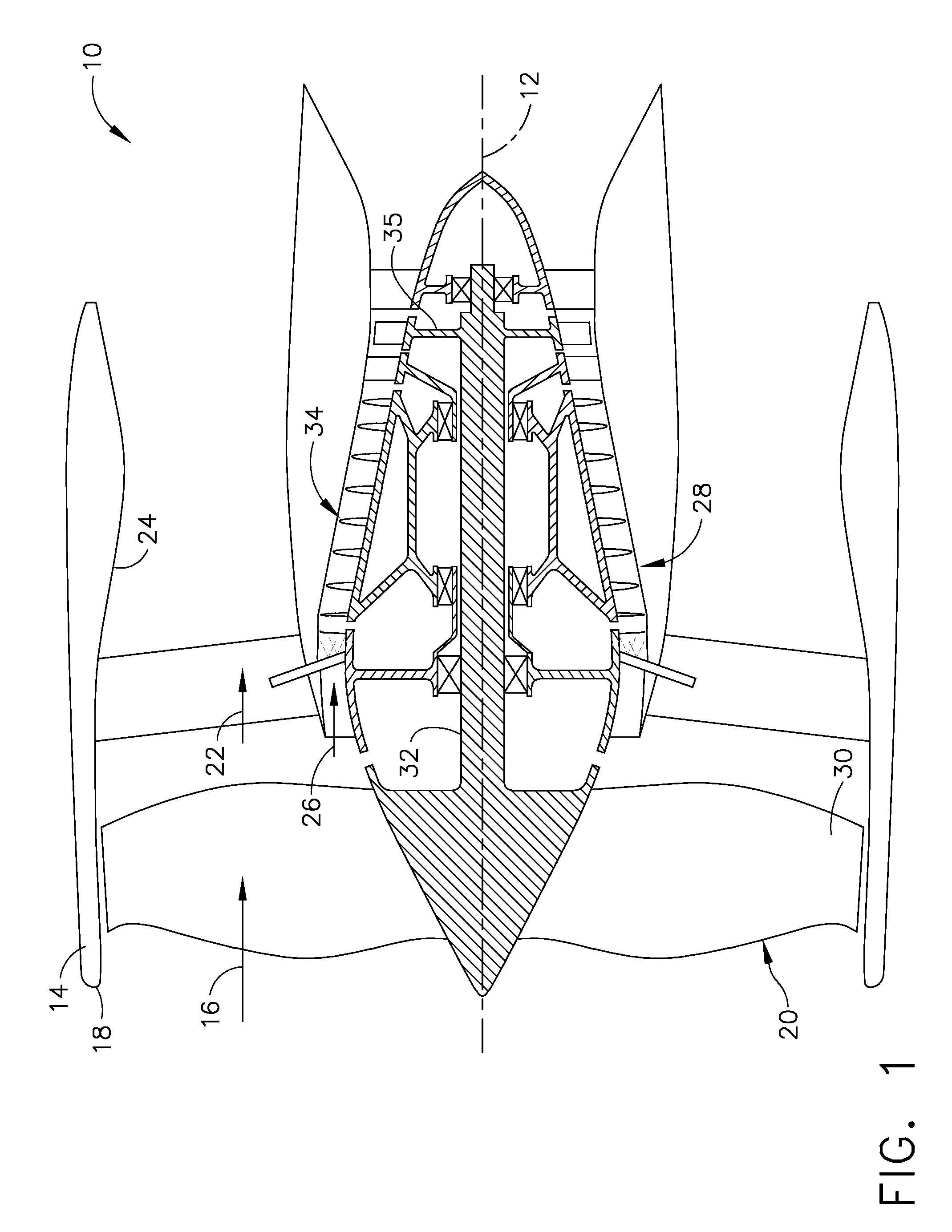
[0023]Referring now to the drawings in detail, wherein identical numerals indicate the same elements throughout the figures, FIG. 1 schematically depicts an exemplary gas turbine engine 10 (high bypass type) utilized with aircraft having a longitudinal or axial centerline axis 12 therethrough for reference purposes. Gas turbine engine 10 includes a nacelle 14 to assist in directing a flow of air (represented by arrow 16) through an inlet 18 to a fan section 20 as is well known. Air flow 16 is then split downstream of fan section 20 so that a first portion (represented by arrow 22) flows through an outer duct 24 and a second portion (represented by arrow 26) is provided to a continuous detonation system 28. A first fan blade row 30 is also preferably connected to a drive shaft 32 which is preferably powered by means of a turbine 35 which receives high pressure combustion gases produced by continuous detonation system 28.

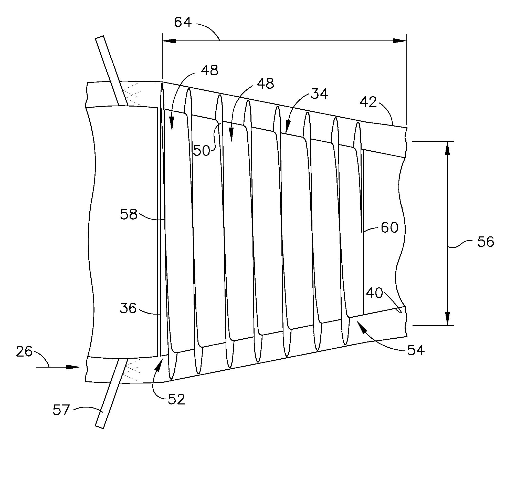
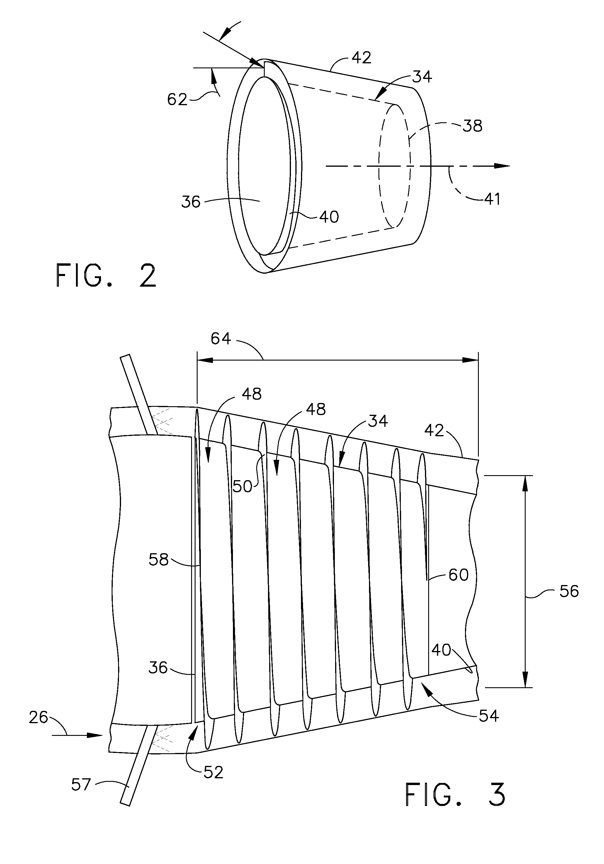
[0024]More specifically, continuous detonation system 28 include...


PUM


Abstract

A continuous detonation system, including: a rotatable member including a forward end, an aft end, a circumferential wall and a longitudinal centerline axis extending therethrough; an outer circumferential wall, wherein the rotatable member is positioned therein so that the circumferential wall of the rotatable member is spaced radially inwardly from the outer circumferential wall; at least one helical channel formed by a plurality of helical sidewalls extending between the circumferential wall of the rotatable member and the outer circumferential wall, each helical channel being open at the forward end and the aft end of the rotatable member so as to provide flow communication therethrough; an air supply for providing air to each helical channel; and, a fuel supply for providing fuel to each helical channel. In this way, a mixture of the fuel and air is continuously detonated within each helical channel in a manner such that combustion gases exit therefrom with an increased pressure and temperature.

Description

CROSS-REFERENCE TO RELATED APPLICATION[0001]The present application is related to an application entitled “Axially Suspended Detonation Combustor For A Gas Turbine Engine,” having Ser. No. ______, which is filed concurrently herewith and is owned by the assignee of the present invention.BACKGROUND OF THE INVENTION[0002]The present invention relates generally to a system and method of continuous detonation in a gas turbine engine and, in particular, to a system and method of continuous detonation in a gas turbine engine where a mixture of fuel and air is continuously detonated in at least one helical channel of a rotatable member to form combustion gases having an increased pressure and temperature.[0003]It is well known that typical gas turbine engines are based on the Brayton Cycle, where air is compressed adiabatically, heat is added at constant pressure, the resulting hot gas is expanded in a turbine, and heat is rejected at constant pressure. The energy above that required to dr...

Claims


Application Information

Patent Timeline
Patent Type & Authority Applications(United States)
IPC IPC(8): F02C3/16F02C3/14
CPCF02C3/14F02C3/16F05D2250/314F05D2250/232F05D2250/25F23R7/00
Inventor MURROW, KURT DAVIDBUTLER, LAWRENCE
Owner GENERAL ELECTRIC CO
Why Eureka
Try Eureka