Apparatus for monitoring the rotational speed in a wind energy plant

a technology for wind energy plants and apparatuses, which is applied in the direction of liquid/fluent solid measurement, devices characerised by mechanical means, devices using electric/magnetic means, etc., can solve the problems of not meeting the safety integrity level and the functional security of rotational speed monitoring, and achieve accurate and reliable analysis of measurement results.

Active Publication Date: 2009-08-06
NORDEX ENERGY SE & CO KG
View PDF15 Cites 33 Cited by
  • Summary
  • Abstract
  • Description
  • Claims
  • Application Information

AI Technical Summary

Benefits of technology

[0007]The apparatus of the present invention serves for monitoring the rotational speed in a wind energy plant. The wind energy plant has a rotor shaft driven by a rotor, which runs out in a gearbox. Further, the wind energy plant has a generator shaft, which connects the output shaft of the gear unit with a generator/converter unit. The apparatus of the present invention is characterised by a first rotational speed detection unit on the rotor shaft and a second rotational speed detection unit on the generator shaft. Each one of the two rotational speed detection units has at least two rotational speed sensors working independently from each other. In addition, an analysing unit for the rotational speed is provided, to which the measured signals of the rotational speed detecti

Problems solved by technology

It has proven to be a drawback of the apparatus for monitoring the rotational speed that the rotational speed monitoring does not have sufficient functiona

Method used


Image

  • Apparatus for monitoring the rotational speed in a wind energy plant
  • Apparatus for monitoring the rotational speed in a wind energy plant

Examples


Embodiment Construction

[0016]While this invention may be embodied in many different forms, there are described in detail herein a specific preferred embodiment of the invention. This description is an exemplification of the principles of the invention and is not intended to limit the invention to the particular embodiment illustrated

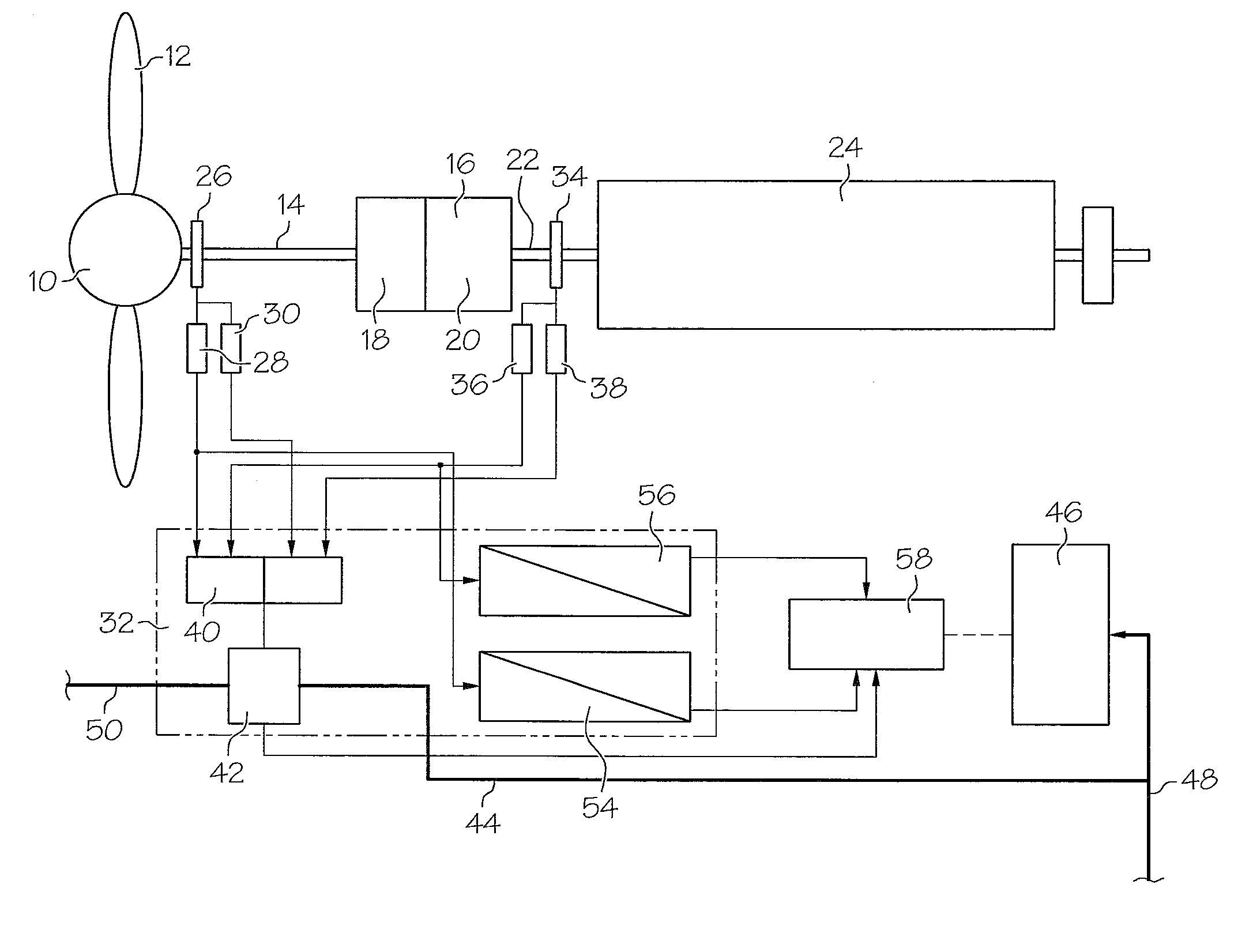
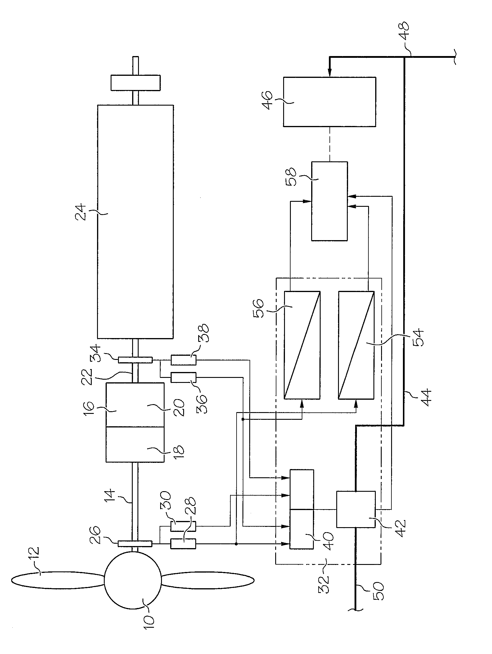
[0017]On the rotor shaft 14, a rotational speed detection unit 26 is provided. The rotational speed detection unit 26 consists of two toothed disks arranged independently on the rotor shaft 14 (not shown), which have a toothing that points radially towards the outside. In the region of the toothing, the toothed disks are provided with a protective coating, which protects the teeth against environmental influences. The two signals of the toothed disks (not shown) are applied to an analysing unit via separated channels 28, 30. In order to form a sufficient functional security for the sensor signals of the rotor shaft, the toothed disks are monitored separately from each other, t...


PUM


Abstract

An apparatus for monitoring the rotational speed in a wind energy plant, with a rotor shaft which is driven by the rotor and runs out into a gear unit, and with a generator shaft, which connects an output shaft of the gear unit with a generator/converter unit, characterised by a first rotational speed detection unit on the rotor shaft and a second rotational speed detection unit on the generator shaft, wherein each rotational speed detection unit has at least two rotational speed sensors working independently from each other, an analysing unit for the rotational speed, to which the measured signals of the rotational speed detection units are applied and which generates an error signal for a rotational overspeed when a certain maximum value for the rotational speed is exceeded.

Description

CROSS-REFERENCE TO RELATED APPLICATIONS[0001]Not applicable.STATEMENT REGARDING FEDERALLY SPONSORED RESEARCH[0002]Not applicable.BACKGROUND OF THE INVENTION[0003]The present invention is related to an apparatus for monitoring the rotational speed in a wind energy plant. Such an apparatus is sometimes also called a rotational speed monitor.[0004]The drive train of a wind energy plant begins with a rotor which carries the rotor blades. The rotor is connected to a rotor shaft, which is coupled to a gearbox. The rotor shaft is sometimes also called a slow shaft. The output shaft of the gearbox runs out into the generator as the generator shaft and is also called the rapid shaft. In known wind energy plants, a toothed disk is arranged on the rotor shaft, which generates pulses via inductive pulse transmitters, the frequency of which is proportional to the rotational speed of the rotor shaft. The pulses are analysed by an electronic module. Also, the sampled pulses are converted into a cu...

Claims


Application Information

Patent Timeline
IPC IPC(8): G01P3/00
CPCF03D7/042F03D11/0091F05B2260/845F05B2270/101F05B2270/327Y02E10/723G01D18/00G01P3/48G01P3/56Y02E10/722F05B2270/809F03D17/00Y02E10/72
Inventor KABATZKE, WOLFGANG
Owner NORDEX ENERGY SE & CO KG
Why Eureka
Try Eureka