Multi-function control valve for fuel vapor system

a multi-functional control valve and fuel vapor technology, applied in functional valve types, lighting and heating apparatus, heating types, etc., can solve the problems of increasing both the size and the complexity of the valve assembly, and achieve the effect of simplifying the structure of the multi-functional control valve assembly and simple configuration

Active Publication Date: 2009-08-06
EATON INTELLIGENT POWER LTD
View PDF10 Cites 25 Cited by
  • Summary
  • Abstract
  • Description
  • Claims
  • Application Information

AI Technical Summary

Benefits of technology

[0010]A feature on the float is operable to provide a metered opening of the vapor vent passage between closed and fully open based on float position to permit venting therethrough. The feature may be a peel-away feature connected to the float that is urged away from the vapor vent passage by the float when flow through the bypass opening equalizes pressures across the housing, reducing buoyancy of the float, tugging on the feature to induce peel away. Because the feature opens in a gradual, metered fashion, it opens under higher pressures than would a relatively large float. The need for a supplemental float that opens to allow venting after closure of the main opening (e.g., by fuel covering the bottom of the valve housing after filling the tank) is avoided. Therefore, only one float controls venting from the chamber, reducing required components necessary for vent-after-closure functioning.
[0012]By creating multiple flow paths and functions all of which are affected by the position of a single float valve, the inventive structure removes the bulk of multiple float valves and simplifies the overall configuration of the multi-function valve while still responding to fuel level and vapor pressure as desired.

Problems solved by technology

The many functions required by the multi-function valve assemblies and the number of valves and flow paths resulting from the functions tend to increase both the size and the complexity of the valve assembly.
The way in which the valves communicate with each other and operate relative to different fuel levels and vapor pressures in the fuel tank often requires complicated routing of fuel vapors around and through the various valves to obtain the desired functions.

Method used


Image

  • Multi-function control valve for fuel vapor system
  • Multi-function control valve for fuel vapor system
  • Multi-function control valve for fuel vapor system

Examples


second embodiment

with Vapor Discriminating Feature

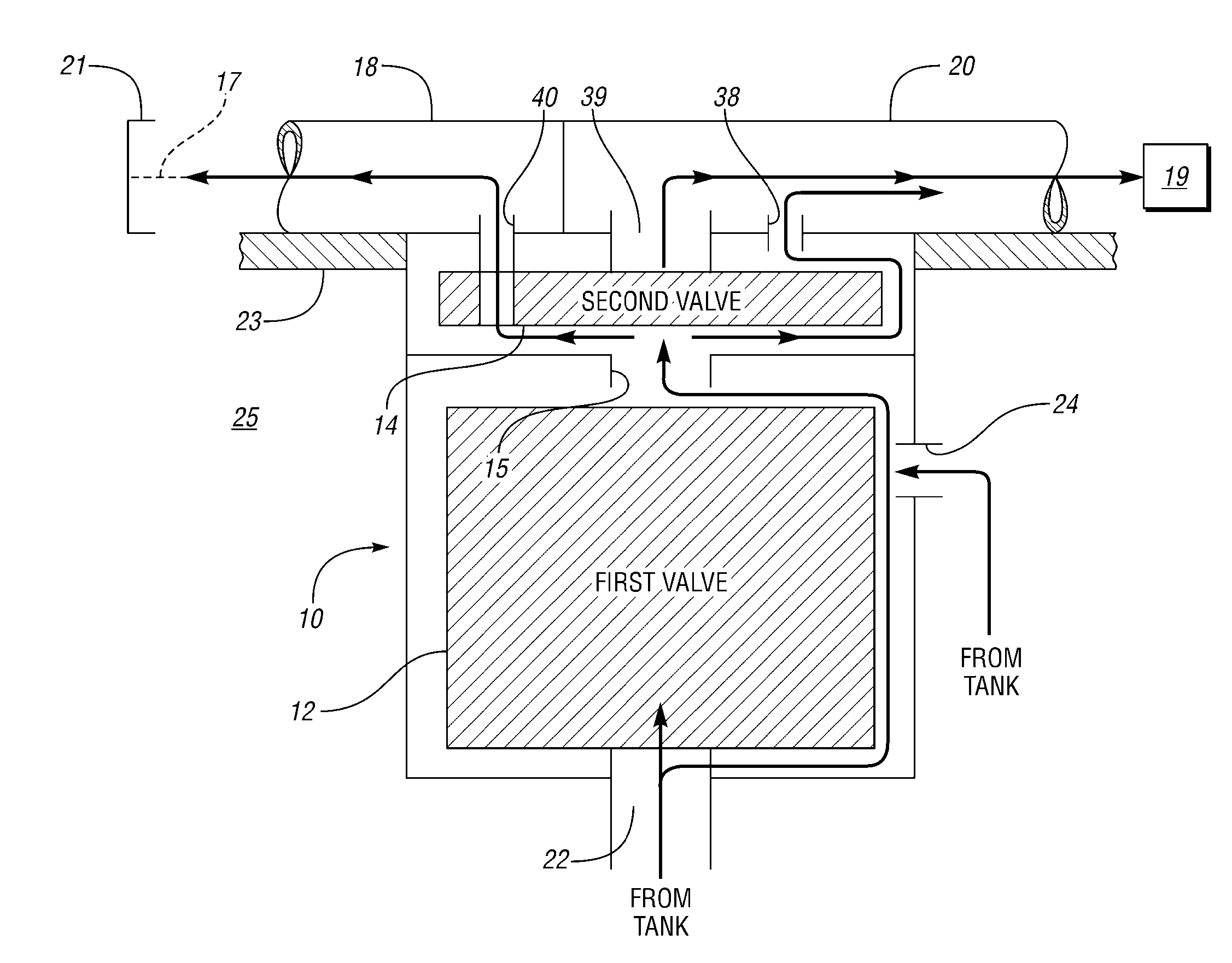
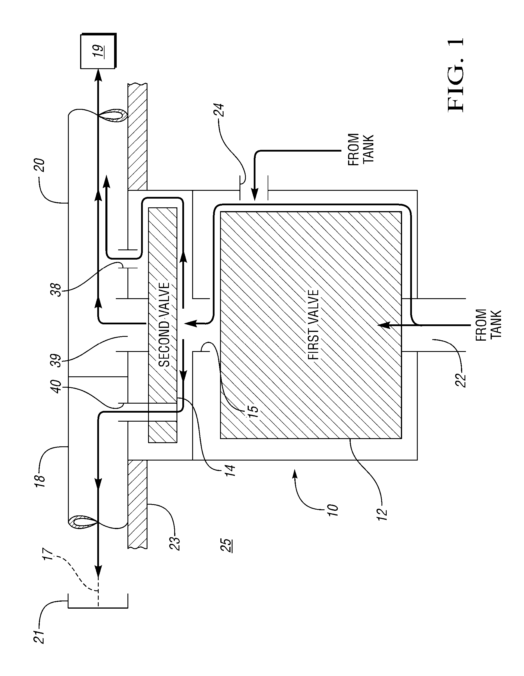
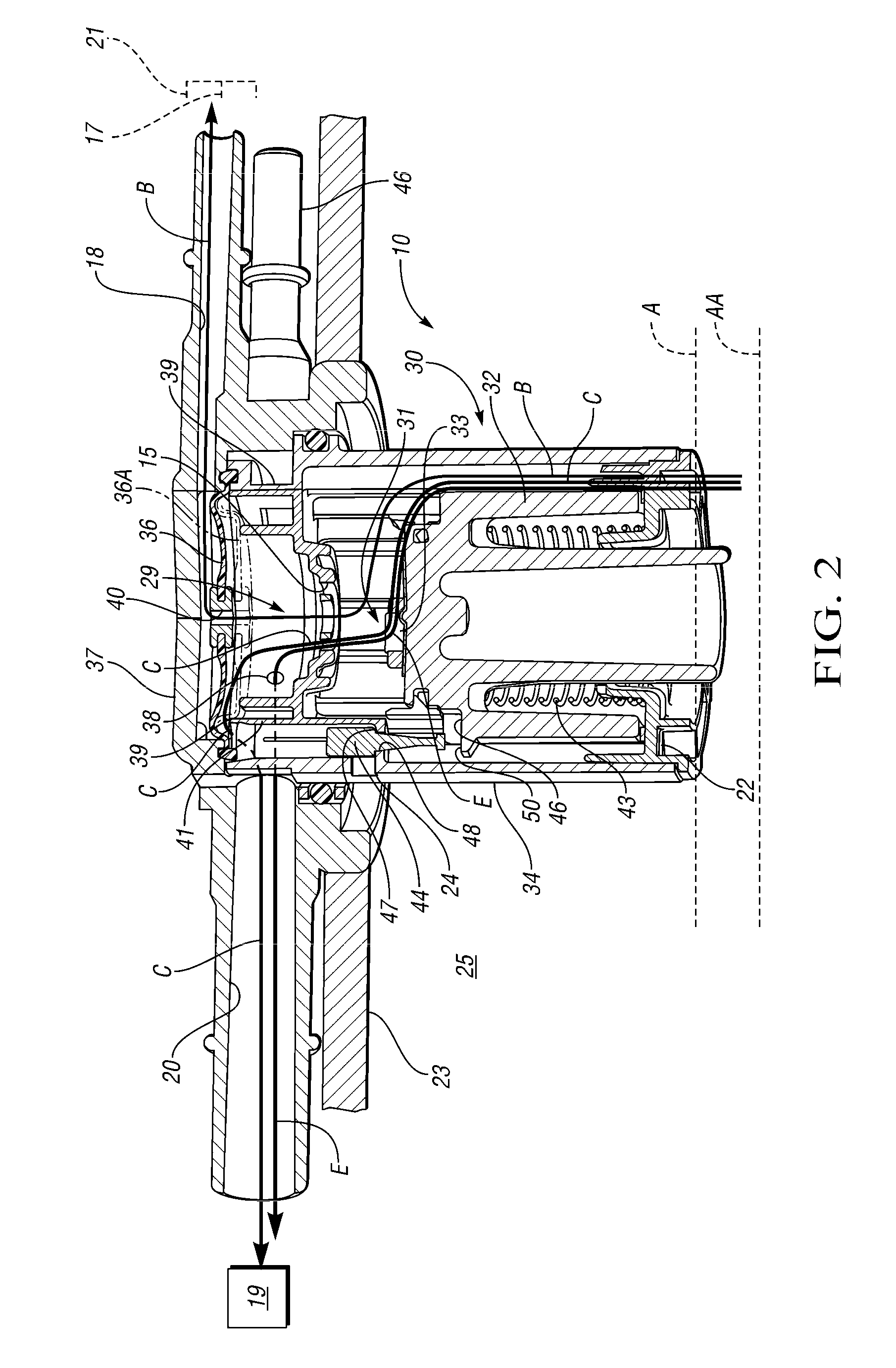
[0034]Referring to FIGS. 6 and 7, another embodiment of a multi-function control valve assembly 110 is shown (only partially shown in FIG. 7). The valve assembly 110 has many of the same components as valve 10, and such are numbered in like manner and perform according to the functions described with respect to valve assembly 10. In particular, a partial tube 158 with an orifice 160 is added between the diaphragm 36A and the opening 15. An additional vapor-discriminating float 162 rests on the housing 134 and is added within tube 158 and supported within the housing 134 above the vapor vent opening 15. During normal run / loss flow, the discriminating float 162 rests on the housing 134 and does not block flow through the orifice 160. Flow from the vapor space 25 thereby proceeds along flow path F through drain opening 22, vapor vent passage 15, opening 160 and opening 39 in the housing 134 to vapor recovery passage 20. When the diaphragm 36A is in the ...


PUM


Abstract

A fuel vapor vent valve assembly is provided that may include a float valve and an isolation valve arranged in series with each other. Bypass openings in the valve assembly create multiple flow paths as the float valve and the isolation valve respond to changes in fuel tank pressure and fuel level. The control valve assembly may include a housing defining a chamber with a main opening configured to open the chamber to the tank, a vapor vent passage and a first bypass vent opening. A float in the chamber closes the vapor vent passage when fuel in the chamber is at or above a predetermined level. The first bypass vent opening vents the tank to the chamber even when the fuel covers the main opening. A feature on the float provides a metered opening of the vapor vent passage between closed and fully open based on float position.

Description

CROSS-REFERENCE TO RELATED APPLICATIONS[0001]This application claims the benefit of U.S. Provisional Application 61 / 025,418, filed Feb. 1, 2008, which is hereby incorporated by reference in its entirety.TECHNICAL FIELD[0002]The present invention relates to vapor vent valves for fuel tanks and more particularly to a vapor vent valve that is float-operated to control fuel vapor flow from the fuel tank to a storage device, such as a canister.BACKGROUND OF THE INVENTION[0003]Float-operated vapor vent valves are often used in fuel tanks to control fuel vapor flow from the fuel tank to a vapor storage device, such as a canister filled with granulated carbonaceous material. Vapor may be controlled by attaching vapor management valves, such as a fuel limit vent valve and grade vent valves to the fuel tank. Typically, each valve is installed separately to the fuel tank by forming an opening in the fuel tank, inserting the valve into the opening, and sealing the valve to the opening to preven...

Claims


Application Information

Patent Timeline
Patent Type & Authority Applications(United States)
IPC IPC(8): F16K24/04F16K17/00B60K15/035
CPCF16K24/044B60K15/035Y10T137/0874Y10T137/3084Y10T137/3087Y10T137/3099
Inventor MARTIN, CHARLES JOSEPHSZLAGA, EMIL
Owner EATON INTELLIGENT POWER LTD
Why Eureka
Try Eureka