Method and device for operating a resistive touch input component as a proximity sensor

a technology of proximity sensor and input component, which is applied in the direction of mechanical pattern conversion, instruments, sustainable buildings, etc., can solve the problem of few proximity sensors capable of operating, and achieve the effect of preventing wrong input detection

Inactive Publication Date: 2009-08-06
NOKIA CORP
View PDF8 Cites 74 Cited by
  • Summary
  • Abstract
  • Description
  • Claims
  • Application Information

AI Technical Summary

Benefits of technology

[0029]This embodiment allows a simple and fast calibration of the proximity functionality of the device, as it is possible to store one (or more) value(s) for defined proximity and non-proximity situations allowing the system to “learn” which detected impedance values are to be used to output a signal indicating a proximity event. Pre-stored impedance data may also be used to define different distances of proximity. Though only a single proximity value may be stored, it is also contemplated to store a number of different stored values enabling the device to output different values of proximity each for different proximity situations.
[0037]That is, the present embodiment may be considered in an embodiment as a method in which the terminal for the upper layer of a resistive touch input device (e.g. a touch screen or a touchpad) is controlled permanently or periodically in a way to determine changes in the capacitance or reactance to use the upper layer as a sensor area of a proximity sensor. To enable a detection of changes in the AC resistance the terminal(s) for the upper layer of the touch component are placed in a high impedance state. In case the upper layer would be in a low impedance state it would be difficult to determine the proximity of an object (which is expected to cause a drop in the impedance). As a drop of a (AC-) resistance can be detected more easily if and when the drop occurs from a high (AC-) resistance, the method uses this fact by setting the upper layer of a touch component to a high impedance state.
[0044]In still another example embodiment of the present invention the method further comprises stop providing said direct current voltage to said (at least one first and) second terminals when a difference between said stored “no proximity value” impedance and said determined impedance does not exceed a predetermined threshold. This embodiment pertains to a situation for saving energy needed for operating the touch input component in case no proximity is detected. This embodiment is based on the assumption that a touch input may only occur when at least a pen or a finger (or another object) of a user touches the surface of the touch input component connected to the device. However, this requires that an object is in close proximity to the touch input component. If no object can be detected, in the proximity, there can be no touch input, and therefore it is not necessary to provide any energy to operate a connected touch input component in a touch input mode. It is also possible to completely deactivate this part of the device provided for detecting and locating a touch input on said touch input component, if no proximity is detected. This may lead to a small contribution in reducing the power consumption of a battery operated mobile electronic device. It may also be envisaged to activate both components only upon a key input for preventing continuous operation of the device if the mobile electronic device using the present invention is carried e.g. in a pocket.
[0046]It is also possible to measure the presence of a proximity while a touch input is detected (i.e. the at least two resistive layers are connected to each other by a pressure exerted on the touch input component). This may be used to notify the user not to touch the screen / touch input component when using e.g. a (e.g. non conductive) stylus for touch input (the stylus may be non conductive to prevent a proximity signal caused by the stylus). This may be used to prevent wrong input detection caused by two touch input, i.e., electric connections between the two resistive layers at two different points.

Problems solved by technology

However, there are only a few proximity sensors available which are capable of being used in connection with small portable devices.

Method used


Image

  • Method and device for operating a resistive touch input component as a proximity sensor
  • Method and device for operating a resistive touch input component as a proximity sensor
  • Method and device for operating a resistive touch input component as a proximity sensor

Examples


Embodiment Construction

[0061]In the detailed description which follows, identical components have been given the same reference numerals, regardless of whether they are shown in different embodiments of the present invention. In order to clearly and concisely illustrate the present invention, the drawings may not necessarily be to scale and certain features may be shown in somewhat schematic form.

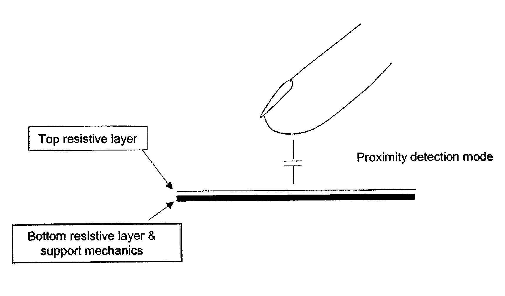
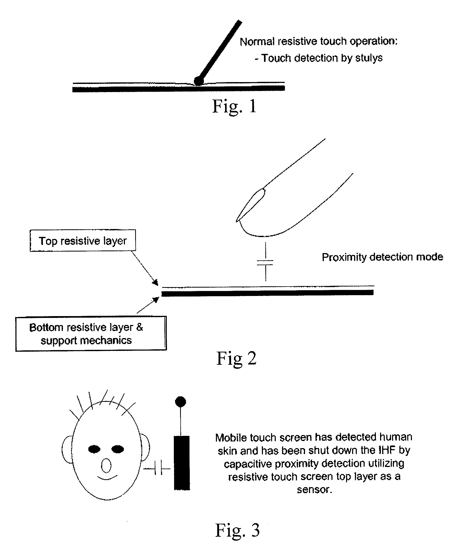
[0062]FIG. 1 depicts a resistive touch input component such as a touch pad or a touch screen. The touch input component has an upper layer and a bottom layer separated by (not depicted) spacer components. As used herein, upper and lower layers refer to a first outboard layer and a second inboard layer without regard to the overall orientation of the device which includes the touch input component. The stylus or pen exerting a force on the upper layer of the touch input device brings the upper conductive layer and the lower conductive layer of the touch input device in electrical (or galvanic) contact. By using a ...


PUM


Abstract

A device is provided which includes a resistive touch input component. The resistive touch input component may operate as a proximity sensor and may include upper and lower conductive layers. The upper conductive layer may be in a higher impedence state than the lower conductive layer. A method for controlling a resistive touch input component is also provided in which at least a first terminal of a device is provided for connecting the upper conductive layer in a high impedence state, and in which at least one second terminal is provided for connecting a lower conductive layer in a state capable of operating the touch input component. Corresponding computer program products and devices are also provided.

Description

BACKGROUND OF THE INVENTION[0001]Presently, there are different proximity sensors available on the market. However, there are only a few proximity sensors available which are capable of being used in connection with small portable devices.[0002]In the US patent application US2007085157 it is disclosed to use a combined proximity sensor / ambient light sensor for use in a mobile device.[0003]From European patent EP 0756733 B1 a low-cost resistive tablet with touch and stylus functionality is known that uses a resistive tablet having a DC driver for resistive detection and the disclosed device also has an AC driver for capacitive finger detection.[0004]Touch devices are becoming more common and many of these devices use proximity sensors to achieve operations such as turning on / off the display during an incoming phone call.[0005]A resistive touch screen panel is composed of several layers. The most common are composed of two thin metallic electrically conductive / resistive layers separat...

Claims


Application Information

Patent Timeline
Patent Type & Authority Applications(United States)
IPC IPC(8): G06F3/041G08C21/00
CPCG06F1/3203G06F1/3231G06F3/0416G06F2203/04108G06F3/045Y02B60/1289G06F3/044G06F1/3265G06F3/0445Y02D10/00
Inventor NOUSIAINEN, JARI
Owner NOKIA CORP
Why Eureka
Try Eureka