Planar microelectromechanical device having a stopper structure for out-of-plane movements

a microelectromechanical device and stopper structure technology, which is applied in the direction of microstructural devices, acceleration measurement using interia forces, microelectromechanical devices, etc., can solve the problems of failure of elastic elements b>5/b>, failure of microelectromechanical devices, and/or damage to other elements of microelectromechanical devices, etc., and achieve the effect of avoiding failure, avoiding failure, and avoiding failur

Active Publication Date: 2009-08-06
STMICROELECTRONICS SRL
View PDF4 Cites 11 Cited by
  • Summary
  • Abstract
  • Description
  • Claims
  • Application Information

AI Technical Summary

Problems solved by technology

This displacement can, in the worst case, even cause failure of the elastic elements 5, and / or damage to other elements of the microelectromechanical device 1 (for example, the mobile mass 2).
However, the depression, which is located close to the mobile mass 2 (in order to limit the range of its movement along the third axis z), gives rise to an undesirable electrostatic interaction with the mobile mass, which can cause undesired displacements thereof and in general malfunctioning of the microelectromechanical device 1.
On the other hand, since the manufacturing process of the microelectromechanical device is a basically planar process, where it is simple to create structures in the xy plane, is not equally simple to obtain them along the third axis z, so that up to now there do not exist valid alternatives to the use of depressions in the package.

Method used


Image

  • Planar microelectromechanical device having a stopper structure for out-of-plane movements
  • Planar microelectromechanical device having a stopper structure for out-of-plane movements
  • Planar microelectromechanical device having a stopper structure for out-of-plane movements

Examples


Embodiment Construction

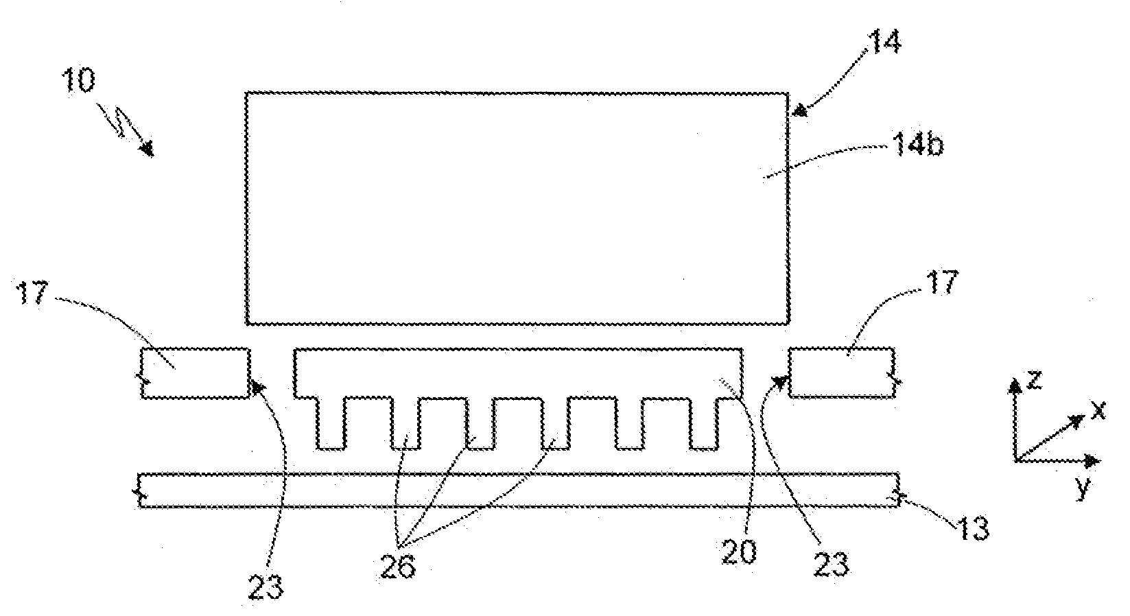
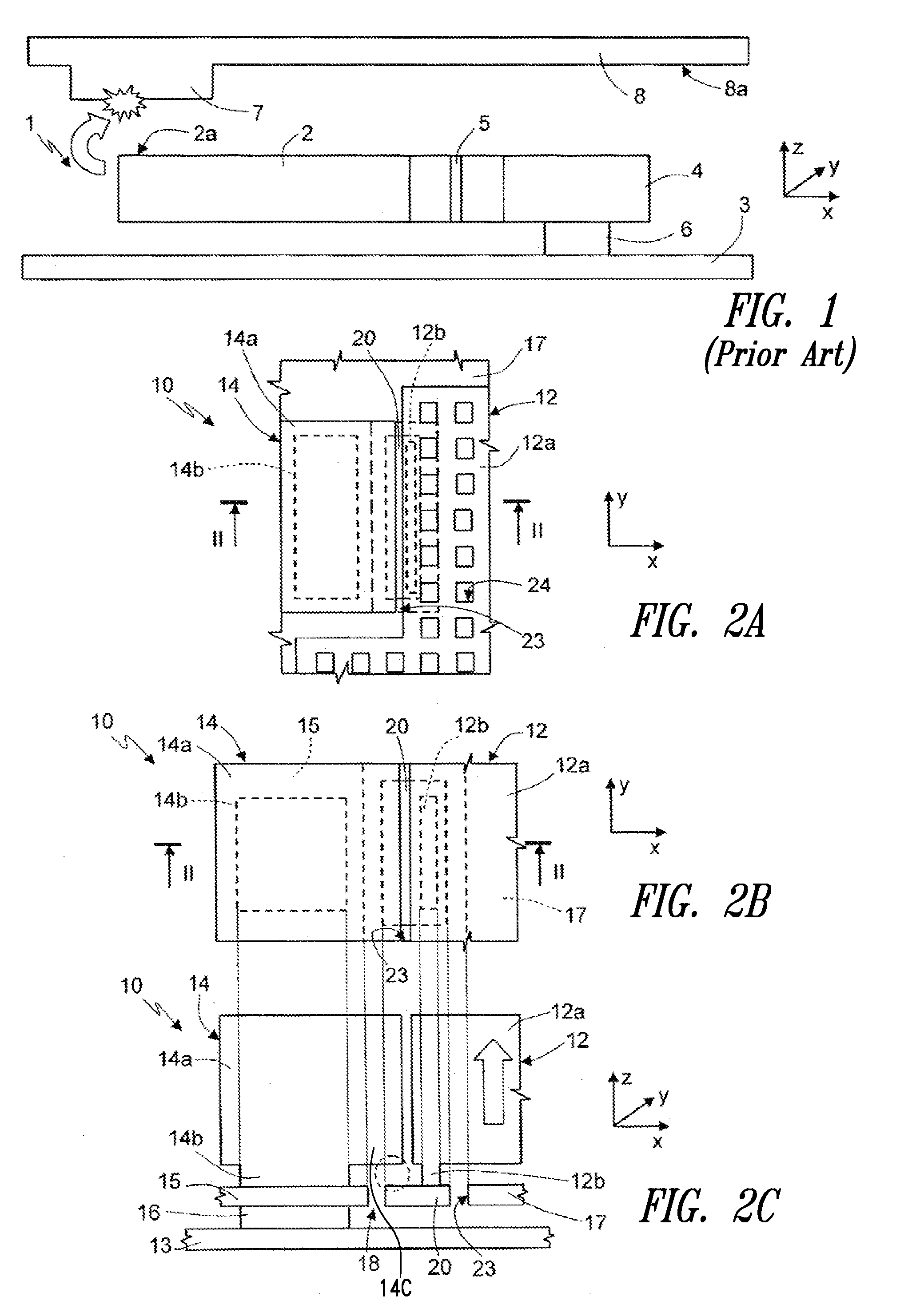
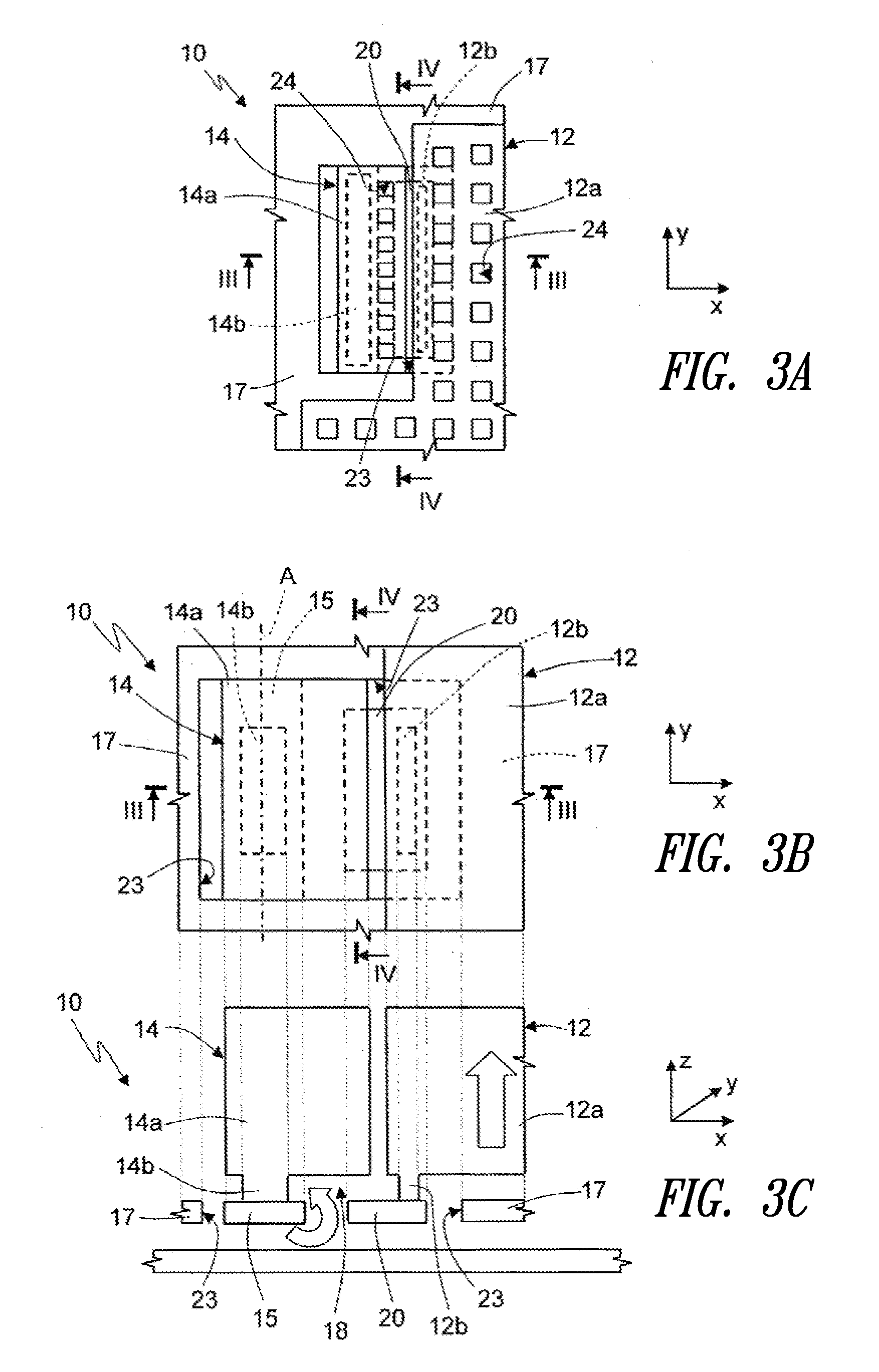
[0022]In detail, and with reference first to FIGS. 2a-2c, a microelectromechanical device 10 comprises a mobile mass 12, in particular an inertial mass (whereof the figures show only one facing portion 12a, for example a terminal edge portion, designed to co-operate, as described hereinafter, with a stopper structure). The mobile mass 12 is suspended over a substrate 13, for example of semiconductor material, and is supported by elastic elements (not illustrated, but could correspond to the elastic elements 5 of FIG. 1) anchored (in a way not shown) to the substrate 13 so as to be free to move in one or more operative directions, for example, along a first axis x and / or a second axis y defining a main plane of extension of the mobile mass.

[0023]The microelectromechanical device 10 further comprises a stopper mass 14, which is arranged facing the mobile mass 12 in a direction parallel to the xy plane, in particular to its facing portion 12a, by means of a respective facing portion 14...


PUM


Abstract

A microelectromechanical device has a mobile mass that undergoes a movement, in particular a spurious movement, in a first direction in response to an external event; the device moreover has a stopper structure configured so as to stop said spurious movement. In particular, a stopper element is fixedly coupled to the mobile mass and is configured so as to abut against a stopper mass in response to the spurious movement, thereby stopping it. In detail, the stopper element is arranged on the opposite side of the stopper mass with respect to a direction of the spurious movement, protrudes from the space occupied by the mobile mass and extends in the space occupied by the stopper mass, in the first direction.

Description

BACKGROUND[0001]1. Technical Field[0002]The present disclosure relates to a planar microelectromechanical device having a stopper structure for out-of-plane movements.[0003]2. Description of the Related Art[0004]Microelectromechanical devices (of a MEMS type), in particular inertial sensors, accelerometers, gyroscopes, etc., are known which base their operation on the presence of suspended structures of semiconductor material, fixed to a substrate at one or more anchorage points and mobile along one or more axes. In particular, the suspended structures form one or more mobile masses, which undergo displacements with respect to the substrate in presence of external stimuli. In the case of sensing structures (for example, accelerometers), first electrodes are associated with the mobile masses and face second electrodes, which are fixed with respect to the substrate, so as to form sensing capacitors, the capacitance of which varies with the displacement of the mobile mass. A suitable e...

Claims


Application Information

Patent Timeline
Patent Type & Authority Applications(United States)
IPC IPC(8): H01H35/14
CPCB81B3/0051B81B2201/0235G01P15/125G01P15/08B81B2201/0242G01P2015/0828
Inventor MERASSI, ANGELOCORTESE, MARIO FRANCESCOVIOLA, FULTIOSIMONI, BARBARARUSCONI CLERICI BELTRAMI, ANDREA
Owner STMICROELECTRONICS SRL
Why Eureka
Try Eureka