Method and apparatus for plating metal parts

a technology of nickelchrome and plating parts, applied in the field of metal electroplating, can solve the problems of inability to plating in the threaded cavity, inability to achieve satisfactory results of any of these methods, etc., and achieve the effect of preventing liquid loss and minimizing liquid carry-over

Active Publication Date: 2009-08-06
CENTURY PLATING
View PDF17 Cites 13 Cited by
  • Summary
  • Abstract
  • Description
  • Claims
  • Application Information

AI Technical Summary

Benefits of technology

[0010]A particular embodiment of the present invention uses a specially designed rack that can hold numerous parts to be plated at the 45 degree down angle (fill position) that can cause the parts to rotate to a 45 degree up position (drain position) and then back down again (fill position) as the rack passes between an arrangement of rollers along the track. The parts can generally all be in the fill position when immersed in cleaning, plating and rinsing solutions. Then, in the cleaning and rinsing stations, they can be shifted to t

Problems solved by technology

However, if a lug nut of this type is simply placed on a rack using a standard spring finger, it has been found

Method used


Image

  • Method and apparatus for plating metal parts
  • Method and apparatus for plating metal parts
  • Method and apparatus for plating metal parts

Examples


Embodiment Construction

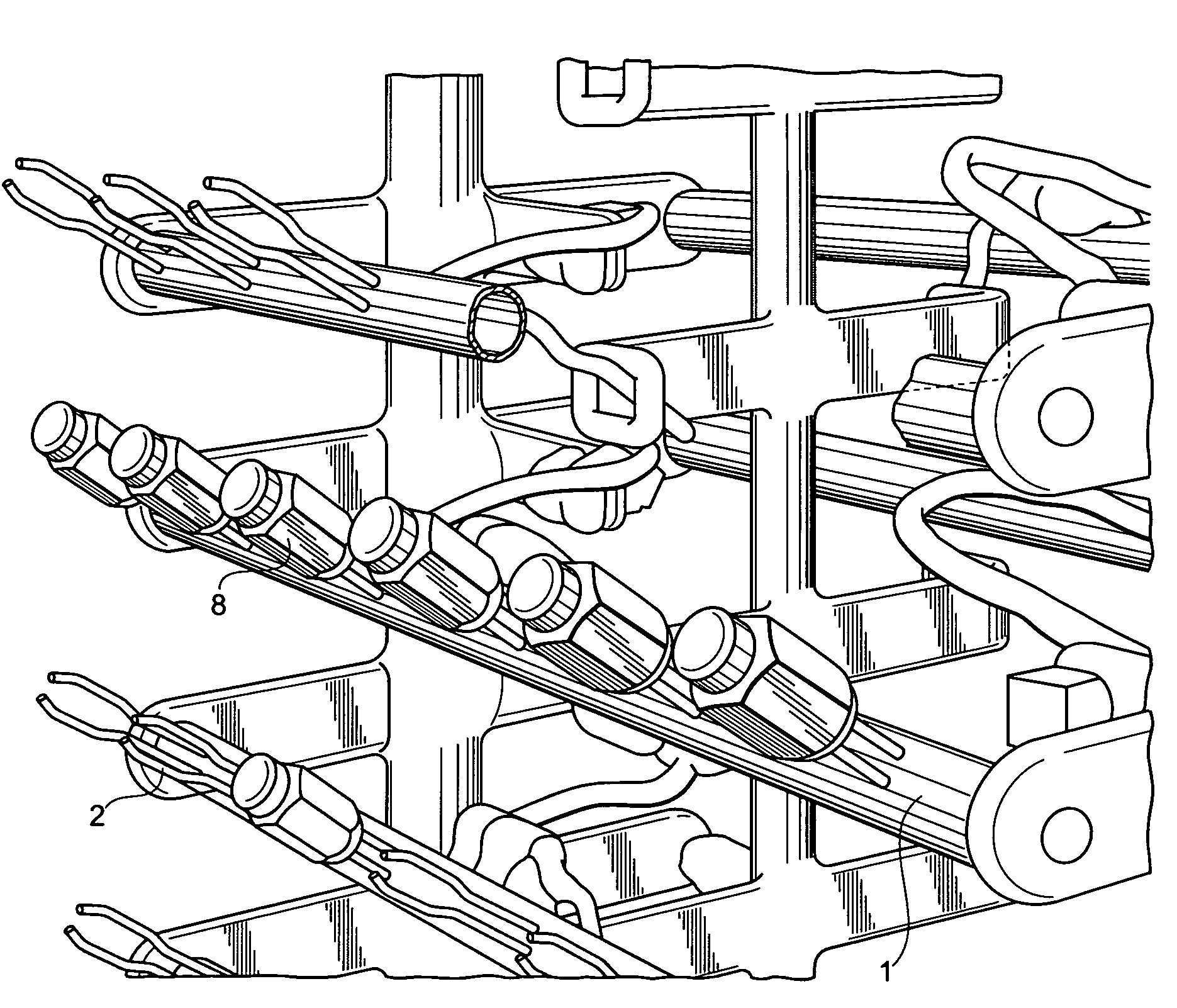
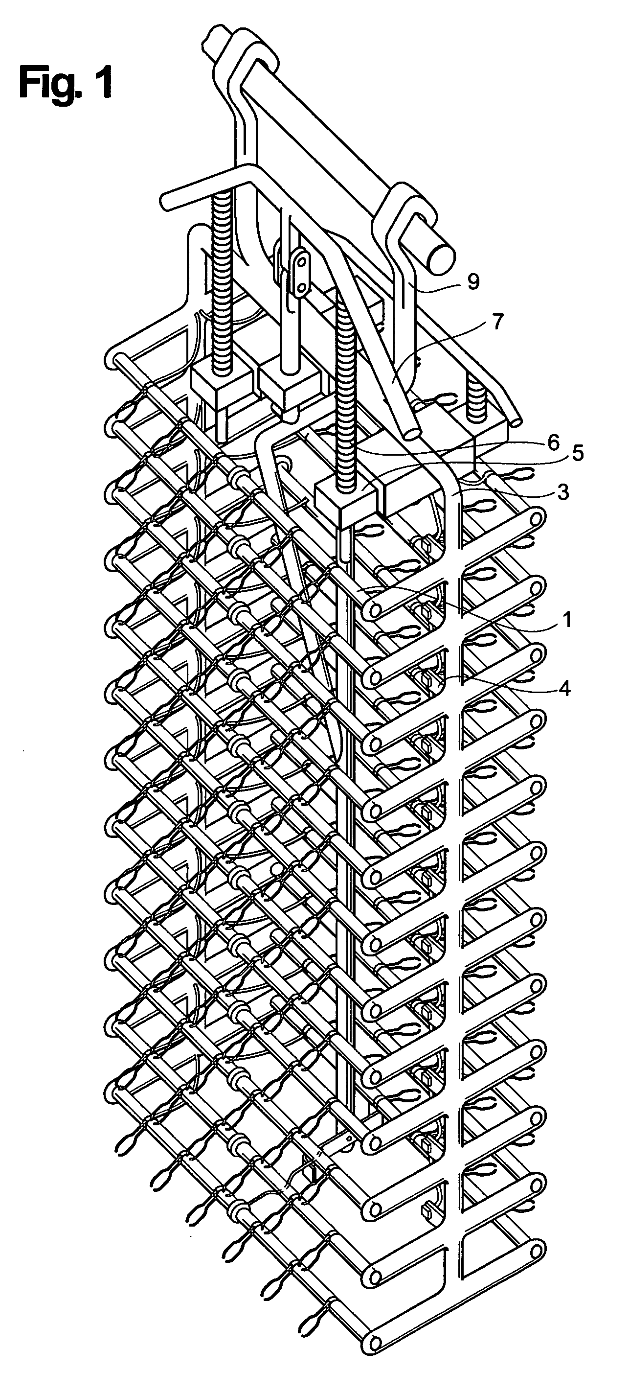
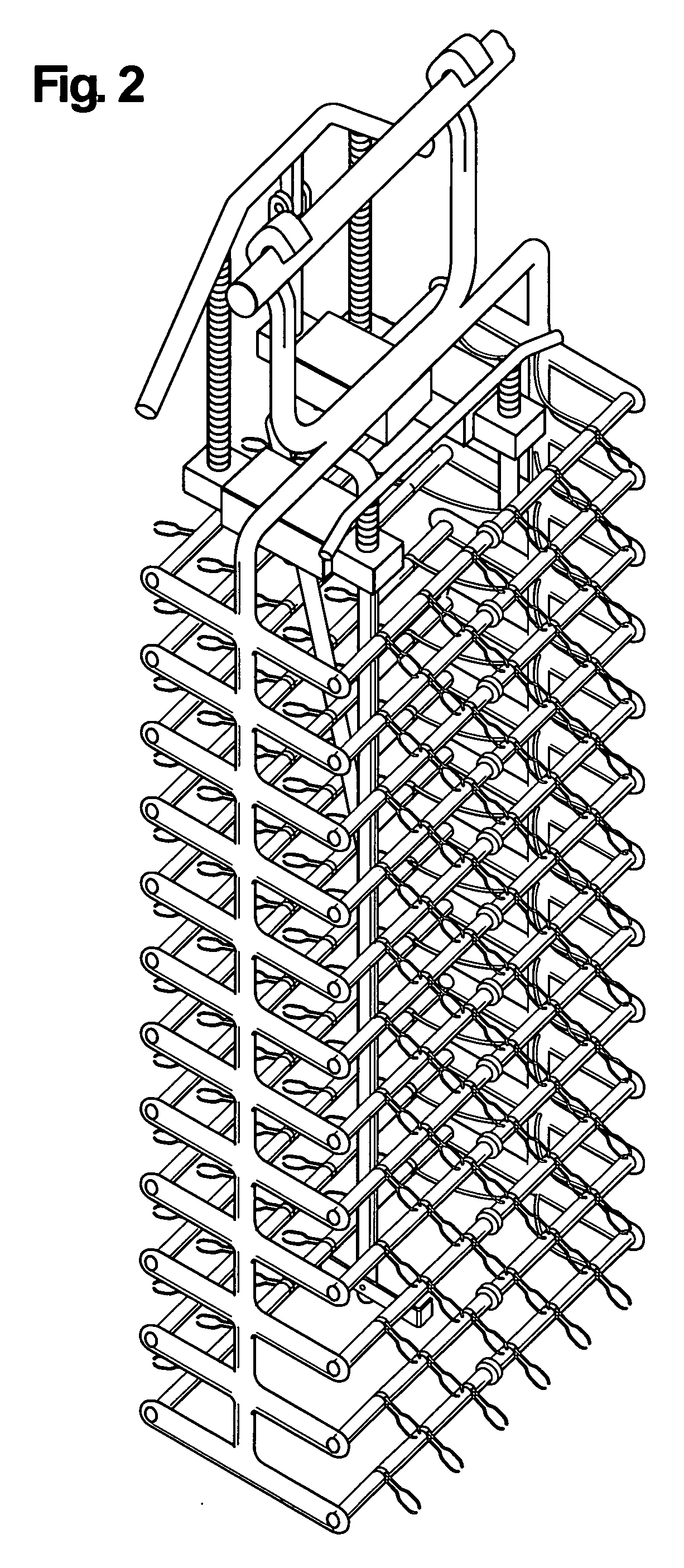
[0027]The present invention relates to a method of plating that involves changing the position of a part containing an internal recess from a fill position to a drain position and back to a fill position while in a plating bath (changing the position with respect to the horizontal plane). The present invention also relates to an apparatus that is a specially designed rack that can hold numerous parts using electrical contact fingers known in the art. This special rack can cause the part to change position from an up or fill position to a down or drain position by depressing a actuator mechanism. Finally, the present invention relates to moving or rotating a part with respect to its electrodes so that plating occurs on the part in locations of finger or other electrode contact.

[0028]Turning to FIGS. 1-2, a rack frame 3 can be seen that holds a number of horizontal rack bars 1. Each rack bar 1 contains several metal fingers 2 protruding outward. Each metal finger 2 is generally a mech...


PUM

PropertyMeasurementUnit
Angleaaaaaaaaaa
Angleaaaaaaaaaa
Areaaaaaaaaaaa

Abstract

A method and apparatus for plating parts like lug nuts or other metal parts that have both an easily plated outside surface as well as a recessed cavity. The invention works in combination with a standard multi-station plating process. Also, a method and apparatus for preventing areas of electrode contact on a part from being non-plated. The present invention drains and plates a part containing a cavity by moving the part from a position where the cavity is facing around 45 degrees down to a position where the cavity is facing around 45 degrees up and then back down at various times during the process. The moving is generally initiated when the rack moving along a track above the fluid tanks encounters a roller. The roller causes a depression bar to activate a mechanical mechanism that shifts the position of the part. Other embodiments of the present invention can also rotate the part on an electrode finger as a roller on the track is encountered by the rack to avoid non-plated regions on the part.

Description

[0001]This application is related to and claims priority from U.S. provisional patent application No. 61 / 063,213 filed Jan. 31, 2008. Application No. 61 / 063,213 is hereby incorporated by reference.BACKGROUND[0002]1. Field of the Invention[0003]The present invention relates generally to the field of metal electroplating and more particularly to a method and apparatus for nickel-chrome plating of parts with internal recesses.[0004]2. Description of the Prior Art[0005]Steel parts may be plated to prevent corrosion and improve appearance. Commercial plating methods many times mount small parts on racks which act as electric cathodes that are passed through numerous electro-chemical plating steps. The parts are generally attached to the rack in a fixed position. This is accomplished by providing attachment points or fingers on the rack that engage the part. These attachment points have conductive tips that act as electrical contacts with the part and also act as mechanical springs to hol...

Claims


Application Information

Patent Timeline
IPC IPC(8): C25D5/00C25D17/00
CPCC25D17/08C25D7/04C25D5/14C25D5/627
Inventor KOLTSE, GEORGELAPORTA, VICTOR
Owner CENTURY PLATING
Why Eureka
Try Eureka