
Heat sink package

Active Publication Date: 2009-08-06
SEMICON COMPONENTS IND LLC
View PDF2 Cites 37 Cited by
  • Summary
  • Abstract
  • Description
  • Claims
  • Application Information

AI Technical Summary

Benefits of technology

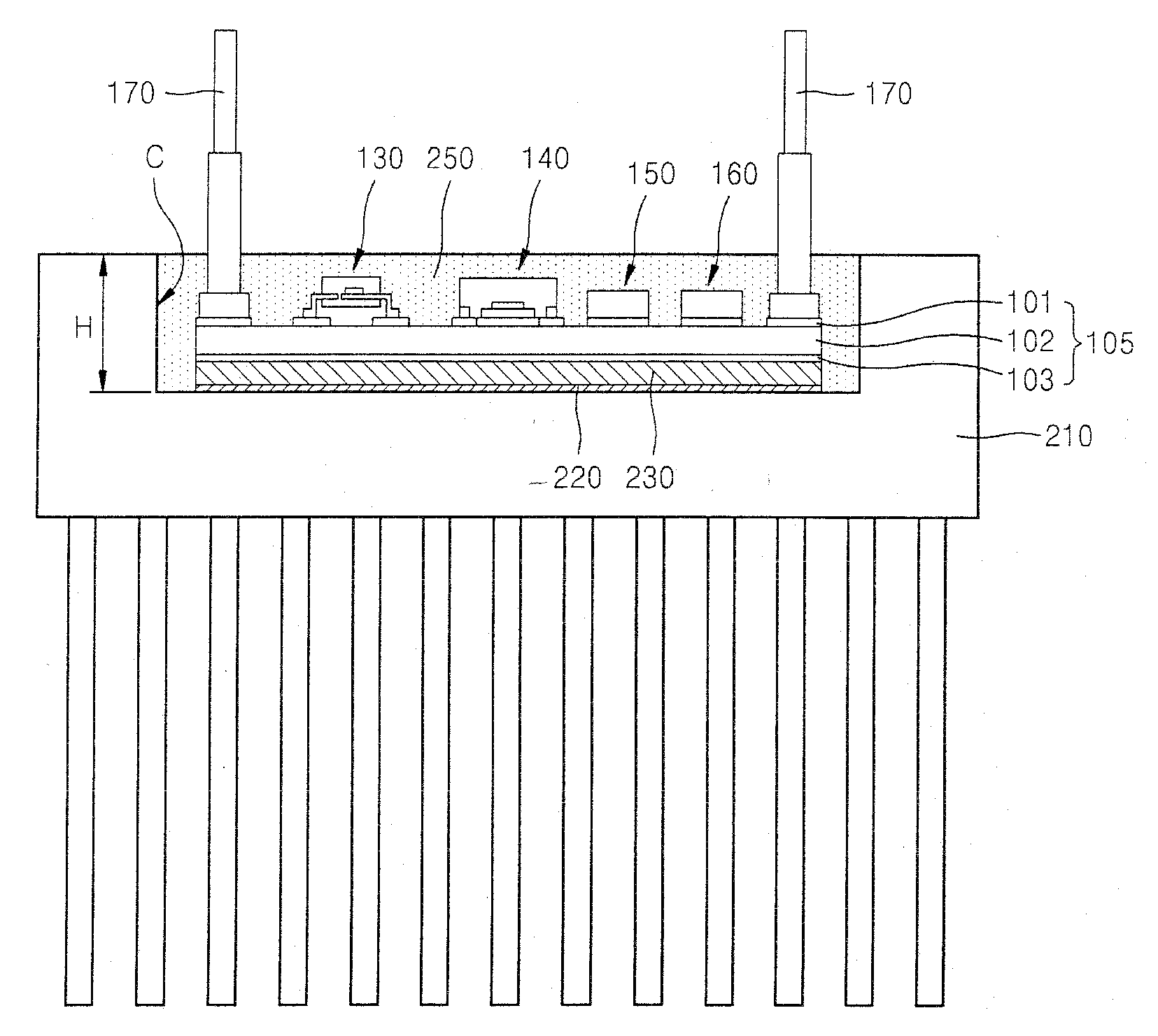
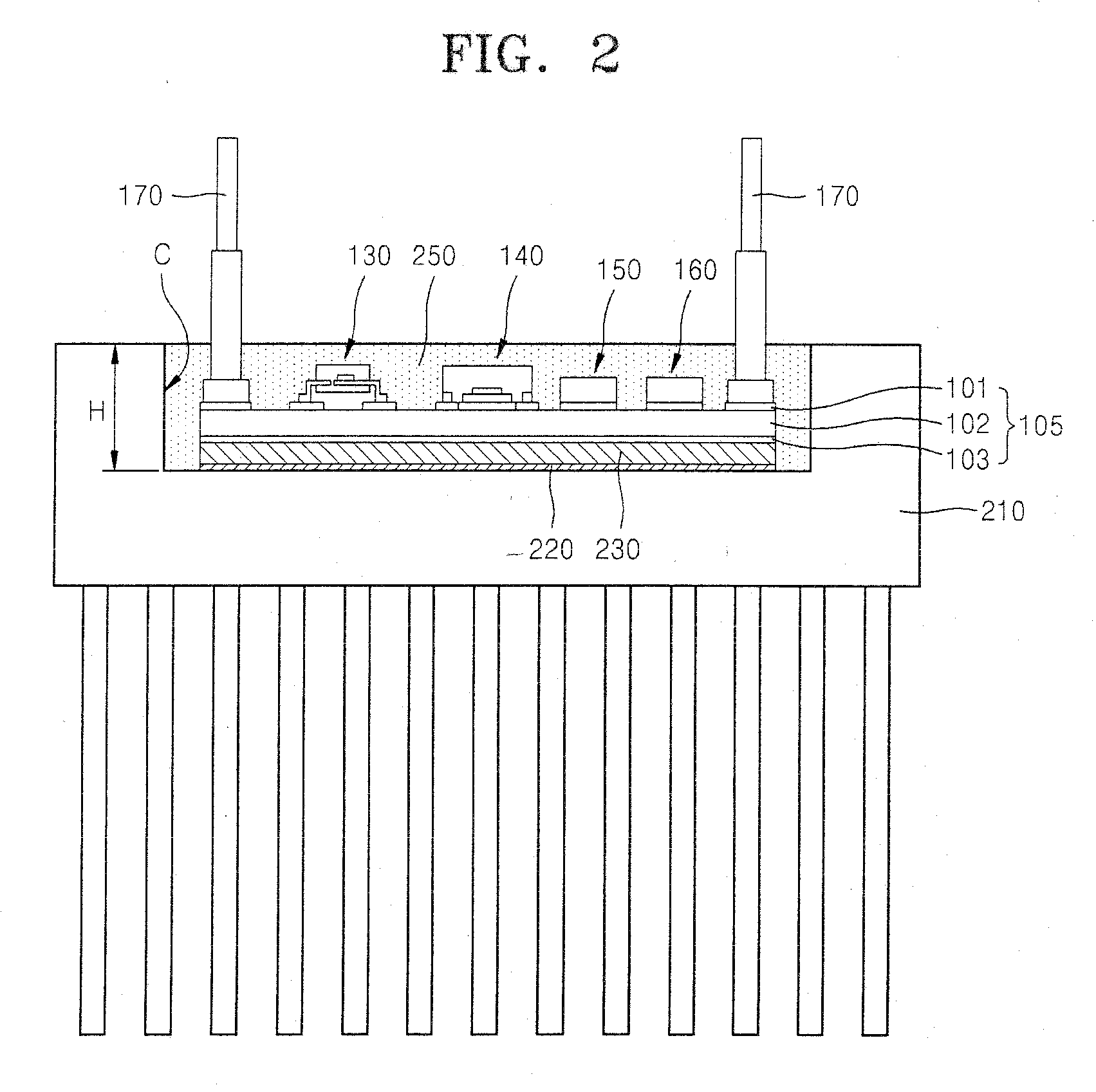
[0013]The present invention provides a heat sink package in which a semiconductor package and a heat sink are bound to each other in order to prevent cracks and warpages and secure low thermal resistance.

Problems solved by technology

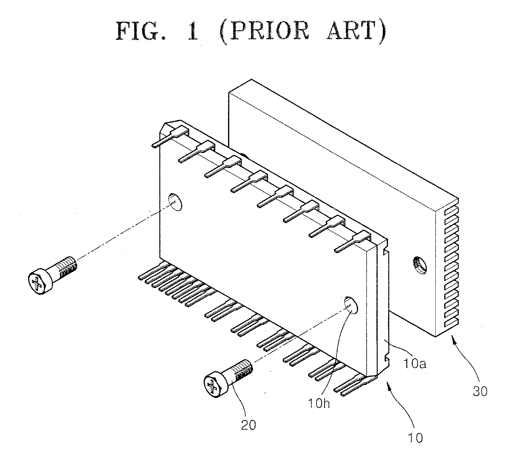
However, the insulation sheet and / or the thermal grease may increase thermal resistance so that reliability or lifetime of the power devices may be decreased.

Method used


Image

  • Heat sink package
  • Heat sink package
  • Heat sink package

Examples


Embodiment Construction

[0028]The present invention will now be described more fully with reference to the accompanying drawings, in which exemplary embodiments of the invention are shown. The present invention may, however, be embodied in many different forms and should not be construed as limited to the exemplary embodiments set forth herein. Rather, these embodiments are provided so that this disclosure will be thorough and complete, and will fully convey the scope of the invention to those skilled in the art. In the drawings, thicknesses of layers and regions may be exaggerated for clarity.

[0029]Like reference numerals in the drawings denote like elements. It will also be understood that when an element such as a layer, a region or a substrate is referred to as being “on” another element, it can be directly on the other element, or intervening elements may also be present.

[0030]Also, spatially relative terms, such as “above” or “upper” and “below” or “lower” and the like, may be used herein for ease of...


PUM


Abstract

Provided are a heat sink package in which a semiconductor package and a heat sink are bound to each other and a method of fabricating the same.The heat sink package includes a heat sink having a cavity on an upper surface thereof; a metal layer formed on the bottom surface of the cavity; a solder paste layer formed on the metal layer; a substrate on the solder paste layer; and a lead and a semiconductor chip mounted on the substrate.

Description

CROSS-REFERENCE TO RELATED PATENT APPLICATION[0001]This application claims the benefit of Korean Patent Application No. 10-2008-0011058, filed on Feb. 4, 2008, in the Korean Intellectual Property Office, the disclosure of which is incorporated herein in its entirety by reference.BACKGROUND OF THE INVENTION[0002]1. Field of the Invention[0003]The present invention relates to a heat sink package in which a semiconductor package and a heat sink are bound to each other and a method of fabricating the same.[0004]2. Description of the Related Art[0005]Generally, a semiconductor package is prepared by mounting a single or a plurality of semiconductor chips on a chip pad in a lead frame, and sealing the chips using a molding member such as epoxy molding compound (EMC) to protect the inside of the semiconductor package, and the semiconductor package is mounted on a printed circuit board (PCB) substrate. Recently, as electronic devices have increasingly been made with high speed, large capaci...

Claims


Application Information

Patent Timeline
IPC IPC(8): H01L23/36
CPCH01L23/367H01L23/3675H01L2924/1305H01L2924/13034H01L2924/13091H01L23/562H01L2924/13055H01L2224/73265H01L2224/48247H01L2224/48091H05K2203/0315H01L25/165H05K1/0306H05K1/053H05K3/0061H05K3/284H05K3/341H05K3/3484H05K2201/0347H05K2201/09745H01L2924/00014H01L2924/00H01L23/3735H05K3/3485H05K7/20H01L23/10
Inventor EOM, JOO-YANGJEON, O-SEOBLIM, SEUNG-WONCHOI, SEUNG-YONG
Owner SEMICON COMPONENTS IND LLC
Features
  • Generate Ideas
  • Intellectual Property
  • Life Sciences
  • Materials
  • Tech Scout
  • Unparalleled Data Quality
  • Higher Quality Content
  • 60% Fewer Hallucinations
Learn More