Chair shell with integral hollow contoured support

a chair shell and support technology, applied in the field of molded chairs, can solve the problems of prone to material failure in the end, and insufficient support of the back portion,

Active Publication Date: 2009-08-06
KRUEGER INT
View PDF26 Cites 22 Cited by
  • Summary
  • Abstract
  • Description
  • Claims
  • Application Information

AI Technical Summary

Problems solved by technology

This chair does not have a back support and therefore may be prone to material failure.
Thus, after repeated use, this area ultimately may be prone to material failure.
In such a situation, the back portion may not provide adequate support due to the degradation of the material joining the seat to

Method used


Image

  • Chair shell with integral hollow contoured support
  • Chair shell with integral hollow contoured support
  • Chair shell with integral hollow contoured support

Examples


Embodiment Construction

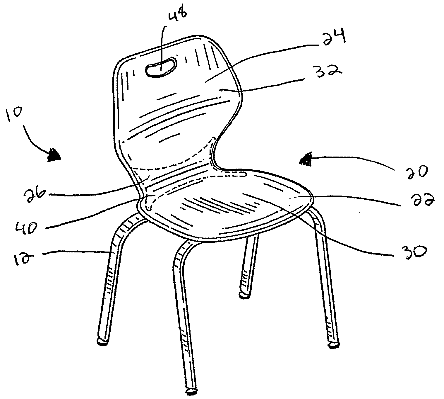
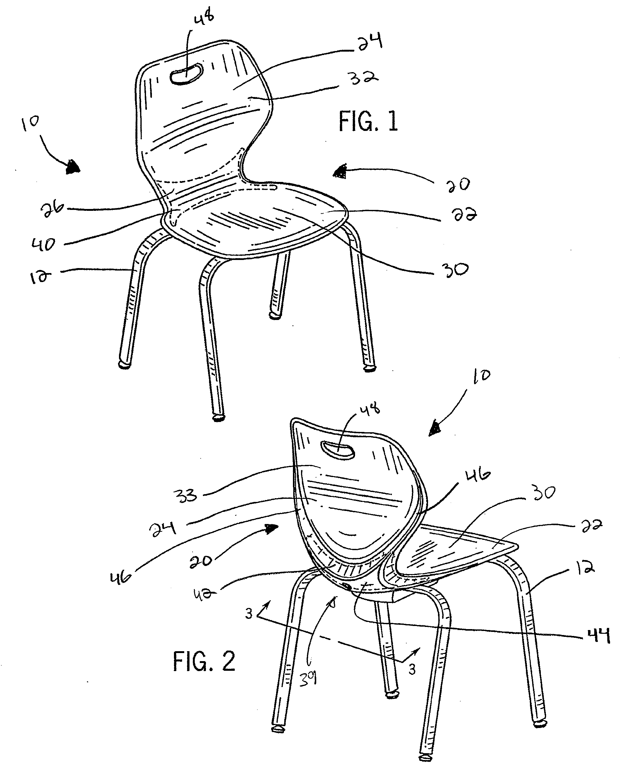
[0019]FIG. 1 illustrates one embodiment of a chair assembly 10 incorporating the chair shell of the present invention. The chair assembly 10 includes a chair shell 20 in accordance with the present invention, and a series of legs 12 attached to the chair shell 20. The chair assembly 10 may use any variety of leg designs known in the art, but preferably the chair assembly features four legs 12 as shown in FIG. 1. The chair shell 20 may be made using any suitable material, e.g., polypropylene, acrylic, polycarbonate, nylon, etc. but preferably it is molded plastic material such as ______.

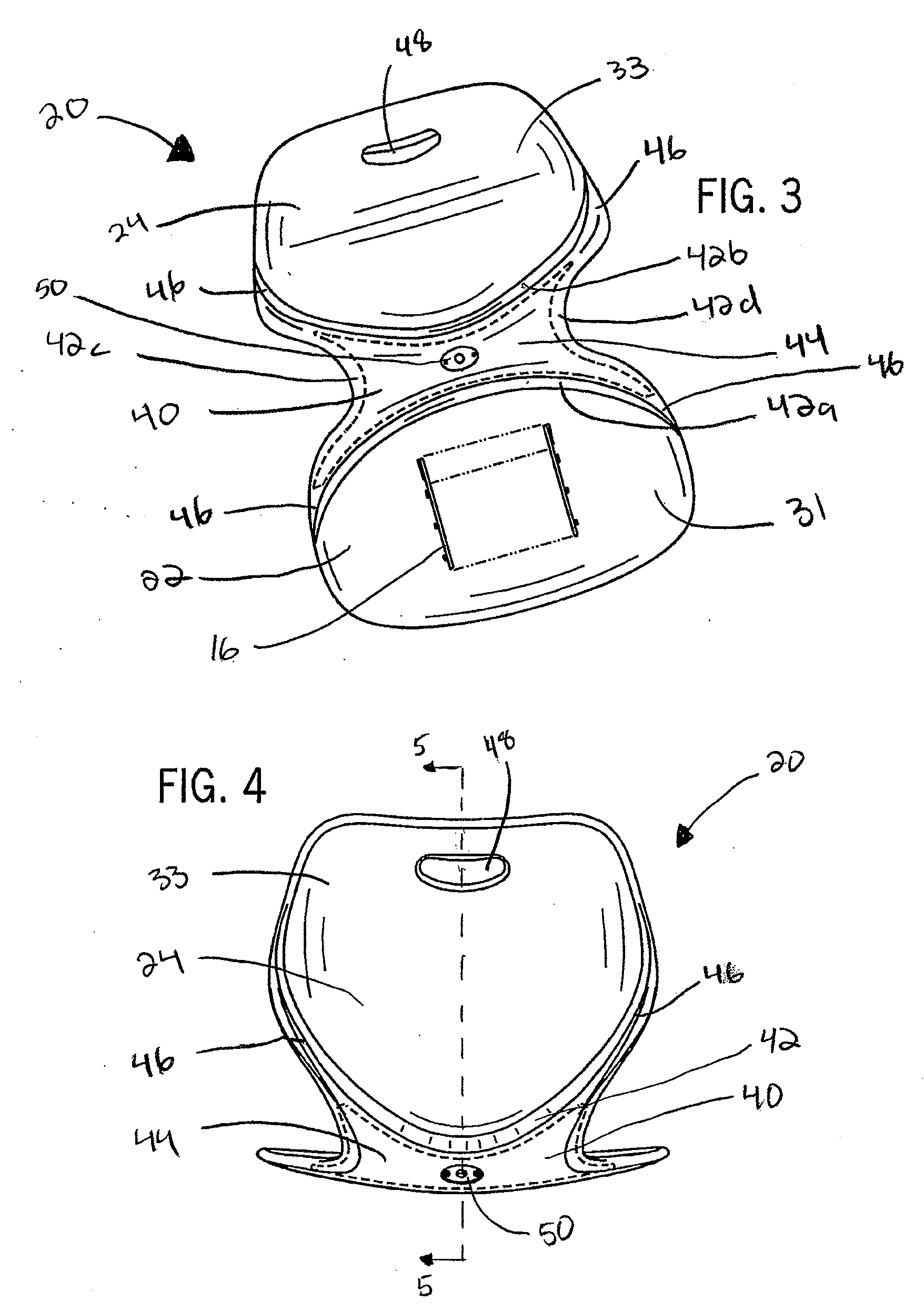
[0020]Generally speaking, the chair shell 20 has a seat portion 22 and an adjacent pack portion 24. The seat portion 22 and the back portion 24 are connected together at a junction area 26. As is well known, the seat portion 22 provides a platform for sitting while the back portion 24 provides support for the user's back. The angle between the seat portion 22 and the back portion 24 be any satisfactor...


PUM

PropertyMeasurementUnit
Widthaaaaaaaaaa
Areaaaaaaaaaaa

Abstract

A molded chair shell includes a seat portion and a back portion joined at a junction area. A support or reinforcement member is located at the junction area and is formed integrally with the seat portion and the back portion. The reinforcement member includes an internal cavity between the seat portion and the back portion that is substantially positioned over the junction area. The cavity is formed by cavity walls, which may form ribs that extend forwardly along the seat portion and upwardly the back portion of the chair shell. The chair shell may be formed in an injection molding process, and the internal cavity may be formed in a gas assist operation carried out during the injection molding process.

Description

BACKGROUND OF THE INVENTION[0001]The present invention relates generally to molded chairs, and more particularly, to a molded chair shell having an integral support member between the seat and the back.[0002]Molded chair shells have been well known in the art for some time. A typical example of a molded chair shell is disclosed in U.S. Pat. No. 3,669,496, which includes a single, molded piece that forms the seat and the seat back. The chair further requires a frame, i.e., a back support, to which the molded piece is attached.[0003]Another example of a molded chair is disclosed in U.S. Pat. No. 3,751,109, which shows a single, molded piece with legs attached at the bottom. This chair does not have a back support and therefore may be prone to material failure. Specifically, when a user sits in the chair and exerts a force on the back portion by leaning back on the back portion, the stress and strain resulting from the force will be concentrated primarily in the area that joins the sea...

Claims


Application Information

Patent Timeline
IPC IPC(8): A47C5/12A47C7/02
CPCA47C5/12A47C3/04
Inventor BOUCHE, TIMOTHY J.HORNBERGER, TIMOTHY G.
Owner KRUEGER INT
Why Eureka
Try Eureka