
Method for Magnetizing Casing String Tubulars

a tubular and casing technology, applied in the field of subterranean borehole drilling and surveying, can solve the problems of significant differences in the imparted magnetization from tubular to tubular, time and labor intensive, and potentially dangerous, and achieve accurate well placement, rapid magnetization, and accurate distance determination

Inactive Publication Date: 2009-08-06
SCHLUMBERGER TECH CORP
View PDF34 Cites 1 Cited by
  • Summary
  • Abstract
  • Description
  • Claims
  • Application Information

AI Technical Summary

Benefits of technology

Enables rapid and repeatable magnetization of a large number of tubulars with consistent magnetic patterns, enhancing the accuracy of well placement and reducing the risk of human error, thereby improving the efficiency and safety of the magnetization process.

Problems solved by technology

While the above described manual method for magnetizing casing tubulars has been successfully utilized, it is both time and labor intensive.
It is also potentially dangerous given the size and weight of a typical casing tubular (e.g., on the order of about 40 feet in length and 1000 pounds or more in weight).
Moreover, such a manual process has the potential to lead to significant differences in the imparted magnetization from tubular to tubular, especially given the sheer number of magnetized tubulars required for a typical SAGD operation.

Method used


Image

  • Method for Magnetizing Casing String Tubulars
  • Method for Magnetizing Casing String Tubulars
  • Method for Magnetizing Casing String Tubulars

Examples


Embodiment Construction

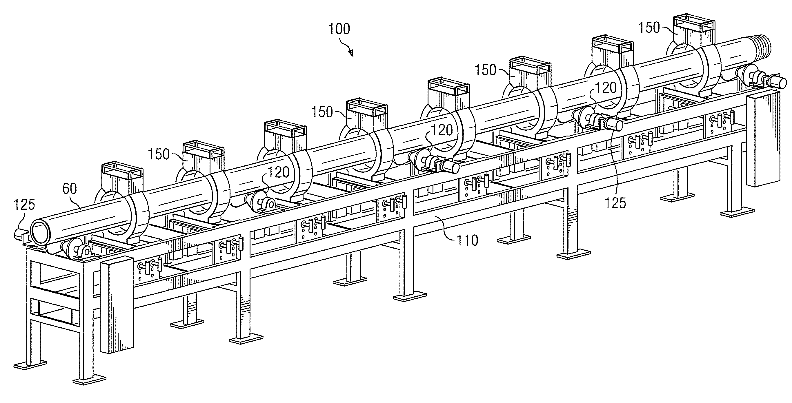
[0026]With reference to FIGS. 2A through 6, it will be understood that features or aspects of the exemplary embodiments illustrated may be shown from various views. Where such features or aspects are common to particular views, they are labeled using the same reference numeral. Thus, a feature or aspect labeled with a particular reference numeral on one view in FIGS. 2A through 6 may be described herein with respect to that reference numeral shown on other views.

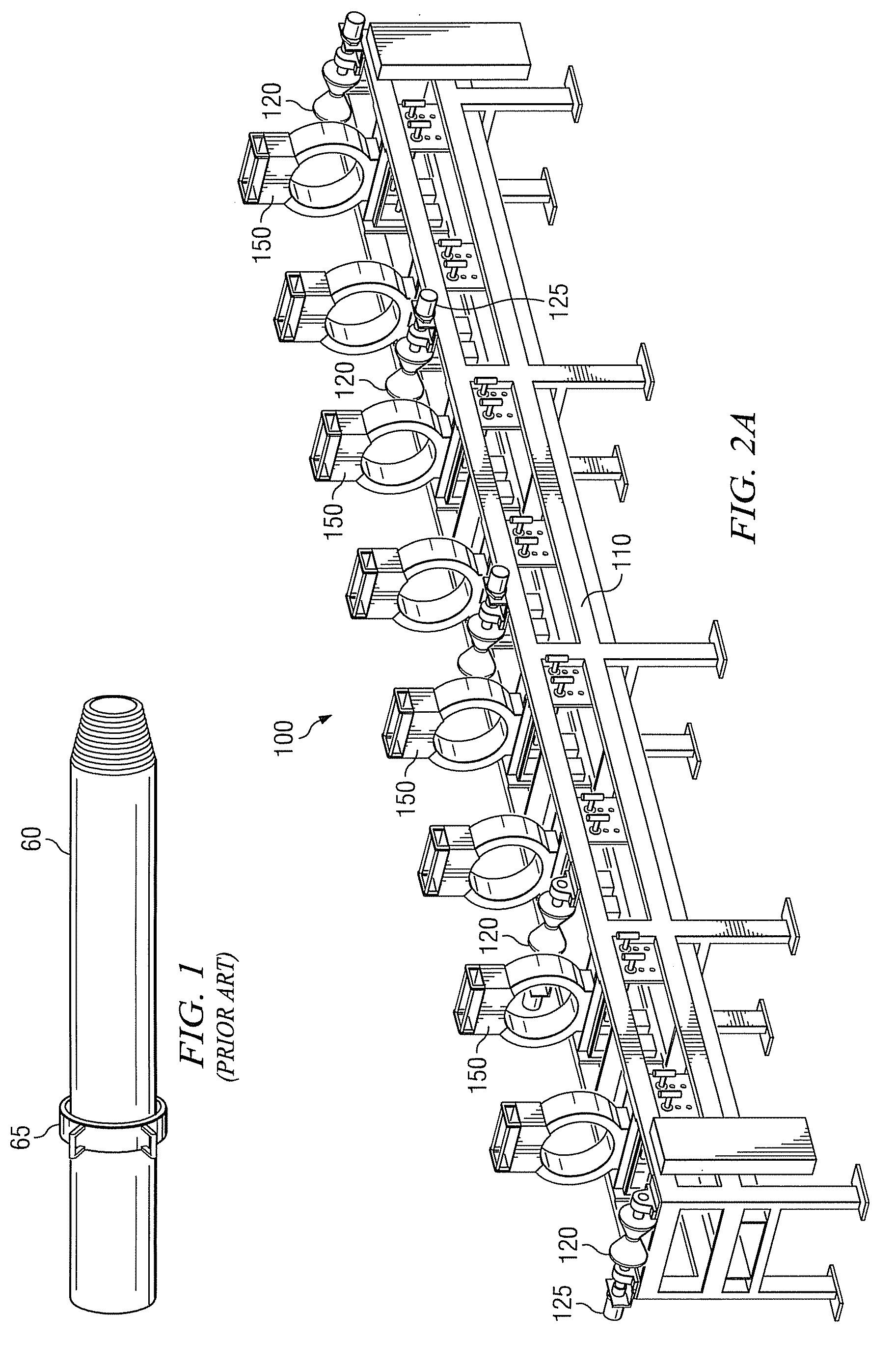
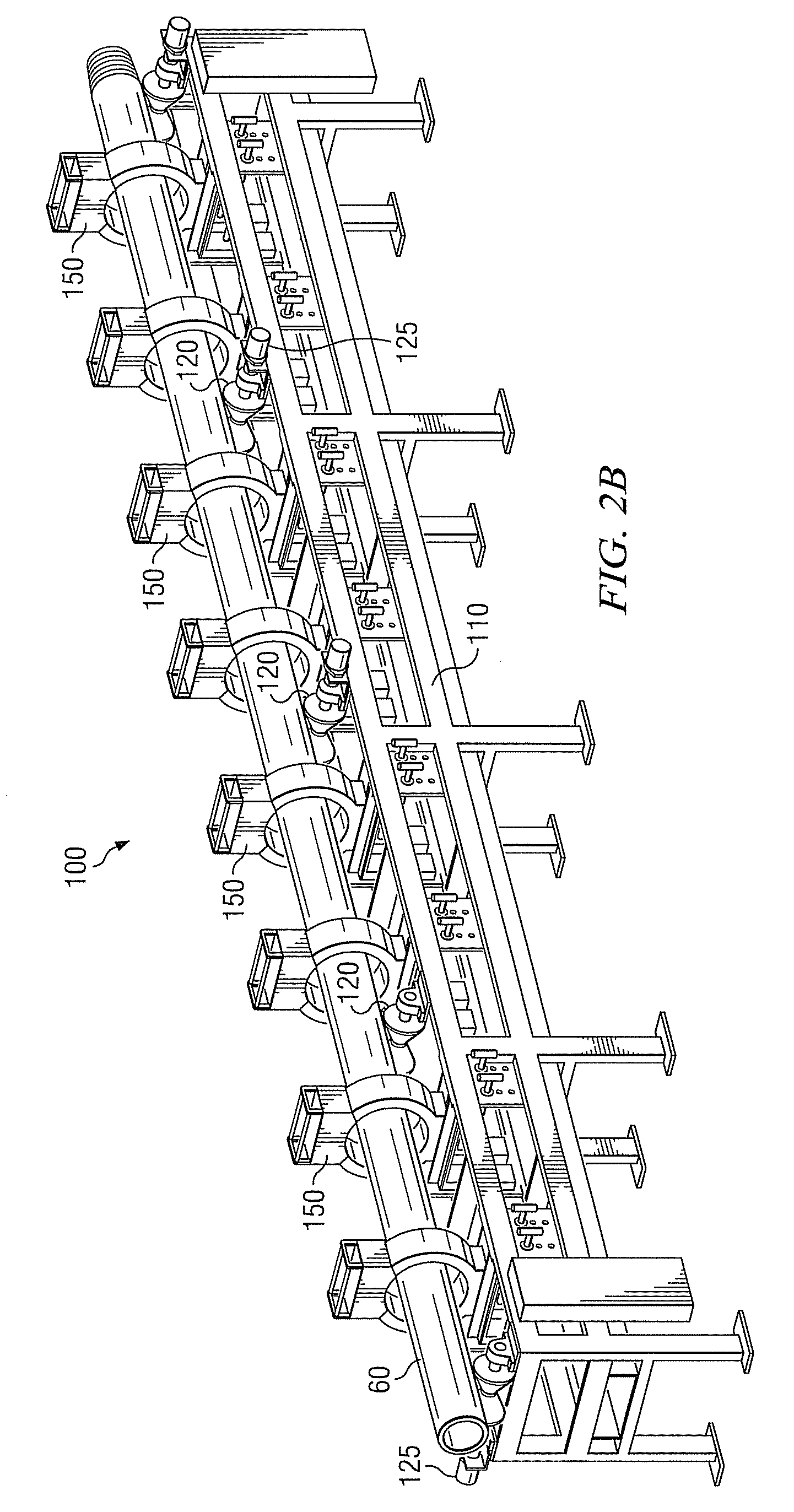
[0027]Referring now to FIGS. 2A and 2B, one exemplary embodiment of an apparatus 100 in accordance with the present invention is shown in perspective view. In FIG. 2B, apparatus 100 is shown with an exemplary tubular 60 deployed therein. Otherwise, FIGS. 2A and 2B are identical. In the exemplary embodiment shown, apparatus 100 includes a plurality of rollers 120 deployed on a nonmagnetic (e.g., aluminum) frame 110. The plurality of rollers may be thought of as a track along which tubulars 60 may be moved in a direction subst...


PUM

PropertyMeasurementUnit
timeaaaaaaaaaa
weightaaaaaaaaaa
lengthaaaaaaaaaa

Abstract

A method for magnetizing a wellbore tubular includes a positioning a wellbore tubular substantially coaxially in a plurality of longitudinally spaced magnetizing coils deployed on a frame. The coils are selectively connected and disconnected from electrical power such that a circumferential electrical current flows in each of the coils to impart a predetermined magnetic field pattern to the tubular. Exemplary embodiments of this invention provide for semi-automated control of tubular magnetization and thereby enable a repeatable magnetic pattern to be imparted to each of a large number of wellbore tubulars.

Description

RELATED APPLICATIONS[0001]This application is a division of U.S. patent application Ser. No. 11 / 487,904, filed Jul. 17, 2006, entitled APPARATUS FOR MAGNETIZING CASING STRING TUBULARS.FIELD OF THE INVENTION[0002]The present invention relates generally to drilling and surveying subterranean boreholes such as for use in oil and natural gas exploration. In particular, this invention relates to an apparatus and method for imparting a predetermined magnetic pattern to a casing string tubular.BACKGROUND OF THE INVENTION[0003]The use of magnetic field measurements in prior art subterranean surveying techniques for determining the direction of the earth's magnetic field at a particular point is well known. Techniques are also well known for using magnetic field measurements to locate subterranean magnetic structures, such as a nearby cased borehole. These techniques are often used, for example, in well twinning applications in which one well (the twin well) is drilled in close proximity and...

Claims


Application Information

Patent Timeline
Patent Type & Authority Applications(United States)
IPC IPC(8): H01F13/00
CPCH01F13/003
Inventor STENERSON, KENNETHCEH, LEONMCELHINNEY, GRAHAM A.
Owner SCHLUMBERGER TECH CORP
Learn More