Display drive apparatus, and display apparatus and display drive method thereof

a technology of display apparatus and drive device, which is applied in the direction of instruments, computing, electric digital data processing, etc., can solve the problems of flicker, the boundary of display regions, and the deterioration of display image quality, so as to suppress the production cost of the display panel. , the effect of difficulty

Inactive Publication Date: 2009-08-06
SOLAS OLED LTD
View PDF3 Cites 26 Cited by
  • Summary
  • Abstract
  • Description
  • Claims
  • Application Information

AI Technical Summary

Benefits of technology

[0012]In view of the problems mentioned above, the present invention accordingly has the advantage of providing a display drive apparatus capable of making it difficult to recognize flickers and the boundaries of display regions of a display panel dealing with an active matrix type drive method, and capable of suppressing a production cost of the display panel, and the advantage of providing a display apparatus equipped with the display drive apparatus and a display drive method thereof.

Problems solved by technology

Consequently, the display operation of a still image has a characteristic in which flickers are difficult to arise, but the display operation of a moving image has a problem in which the image information displayed in the preceding frame period is easily sighted as a residual image and the blurring and bleeding of the image information are caused to cause the deterioration of a display image quality.
However, even if the frame frequency (that is, the drive frequency of a display apparatus) is set to be higher, there is a problem in which flickers and the boundaries of display regions (boundaries between emission regions and non-emission regions) are sometimes recognized when a human visual line quickly moves.
Moreover, there are also the problems of causing the rise of a driver cost and the restriction of the specifications of a display panel.

Method used


Image

  • Display drive apparatus, and display apparatus and display drive method thereof
  • Display drive apparatus, and display apparatus and display drive method thereof
  • Display drive apparatus, and display apparatus and display drive method thereof

Examples


first embodiment

[0085]First, a schematic configuration of a display apparatus according to the present invention will be described with reference to the attached drawings.

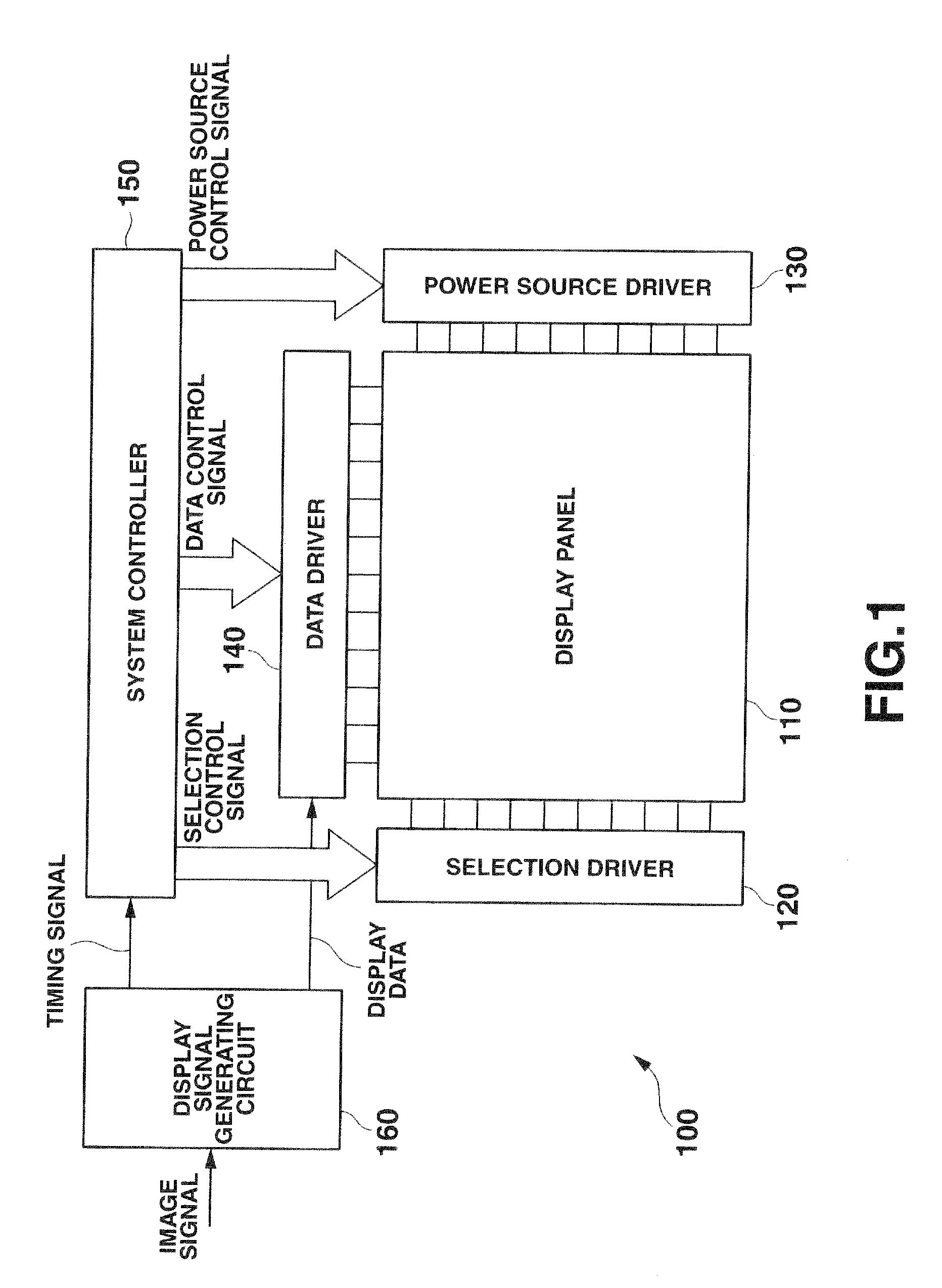
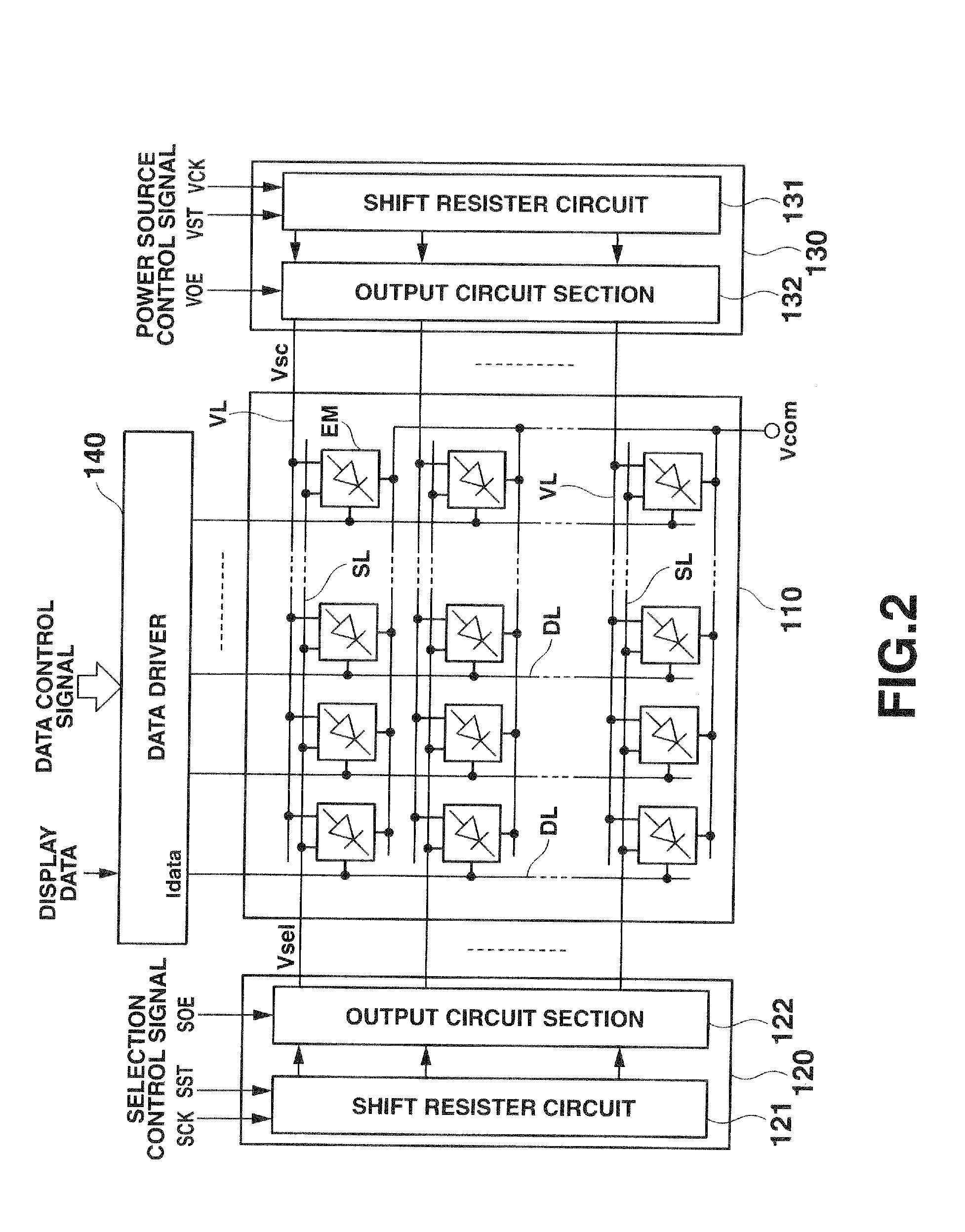
[0086]FIG. 1 is a schematic block diagram showing an example of the whole configuration of a display apparatus according to the present invention, and FIG. 2 is a diagram of the configuration of the principal part showing the examples of a display panel and the peripheral circuitry thereof (a selection driver, a data driver, and a power source driver) applied to a display apparatus according to a first embodiment.

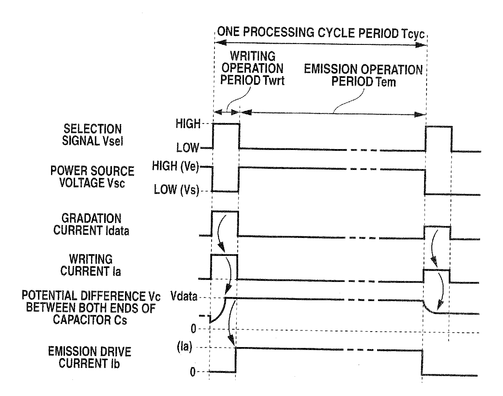
[0087]Incidentally, an emission element type display apparatus will be described in the embodiments shown in the following. Each of the emission element type display apparatus has a configuration in which a plurality of display pixels is two-dimensionally arranged as a display panel. Each display pixel includes an emission element, and each display pixel performs an emission operation with a luminous gradation according t...

second embodiment

[0145]Next, a second embodiment of the display apparatus according to the present invention will be described.

[0146]In regard to the aforesaid first embodiment, the description has been given to the case where, when a writing operation into the display pixels in each row of the display panel is executed, the display pixels in a row (designated line) separated from the row (writing line) into which the writing operation is executed by the predetermined number of rows are set to be in their non-emission states together with the writing line. In the second embodiment, a display panel is grouped every display pixels in a plurality of continuous rows, and the writing operation into each row is executed by the group. Furthermore, the second embodiment controls the display pixels in the group (hereinafter referred to as “designated group” for descriptive purposes) separated from the group (hereinafter referred to as “writing group” for descriptive purposes) including the rows (writing line...

third embodiment

[0176]Next, a third embodiment of the display apparatus according to the present invention will be described.

[0177]In regard to the aforesaid first embodiment, the description has been given to the case where, when a writing operation into the display pixels in each row of the display panel is executed, the display pixels in a row (designated line) separated from the row (writing line) into which the writing operation is executed by the predetermined number of rows are set to be in their non-emission states together with those in the writing line. In this case, although the description has been given to the case where the rows set to be as the non-emission states are two rows of the writing line and the designated line separated from the writing line by the predetermined number of rows, but the third embodiment controls so as to set a plurality of rows separated from each other by the predetermined number of rows as the designated lines in addition to the row separated from a writin...


PUM


Abstract

A display drive apparatus performs a display drive of a display panel on the basis of display data and comprises a selection drive section for applying a selection signal to each of display pixels arranged in each row of the display panel, a data drive section for generating a drive signal based on the display data, and a power source drive section for setting at least a row as a writing region and at least a region as a designated region separated from the writing region by the number of one or more rows and sequentially moving correspondingly to moving of the writing region, and the power source drive section supplies a power source voltage for operating each display pixel to make each display pixel corresponding to the row of the writing region and each display pixel corresponding to the row of the designated region perform non-display operation.

Description

CROSS-REFERENCE TO RELATED APPLICATIONS[0001]This application is based upon and claims the benefit of priorities from the prior Japanese Patent Application No. 2008-024759, filed Feb. 5, 2008, and No. 2008-052926 filed on Mar. 4, 2008, the entire contents of which are incorporated herein by reference.BACKGROUND OF THE INVENTION[0002]1. Field of the Invention[0003]The present invention relates to a display drive apparatus, and a display apparatus and display drive method thereof, and more particularly to a display drive apparatus for driving a display panel dealing with an active matrix type drive method, a display apparatus equipped with the display drive apparatus, and a display drive method thereof.[0004]2. Related Art[0005]In recent years, a display apparatus (emission element type display apparatus), equipped with a liquid crystal display device (LCD) or a display panel in which self-emission elements, such as organic electroluminescence elements (organic EL elements), are two-d...

Claims


Application Information

Patent Timeline
Patent Type & Authority Applications(United States)
IPC IPC(8): G06F3/038
CPCG09G3/3233G09G3/325G09G3/3258G09G3/3283G09G2300/0842G09G2330/021G09G2310/0218G09G2310/0256G09G2320/0247G09G2330/02G09G2300/0866
Inventor OZAKI, TSUYOSHI
Owner SOLAS OLED LTD
Why Eureka
Try Eureka