Noise canceller as well as high-frequency receiver and portable device each using the same
a high-frequency receiver and noise canceller technology, applied in the field of noise cancellers, can solve the problems of user failure to watch a television program, degrade the reception sensitivity of the portable device, etc., and achieve the effect of suppressing the noise signal and improving the reception sensitivity
- Summary
- Abstract
- Description
- Claims
- Application Information
AI Technical Summary
Benefits of technology
Problems solved by technology
Method used
Image

Examples
first embodiment
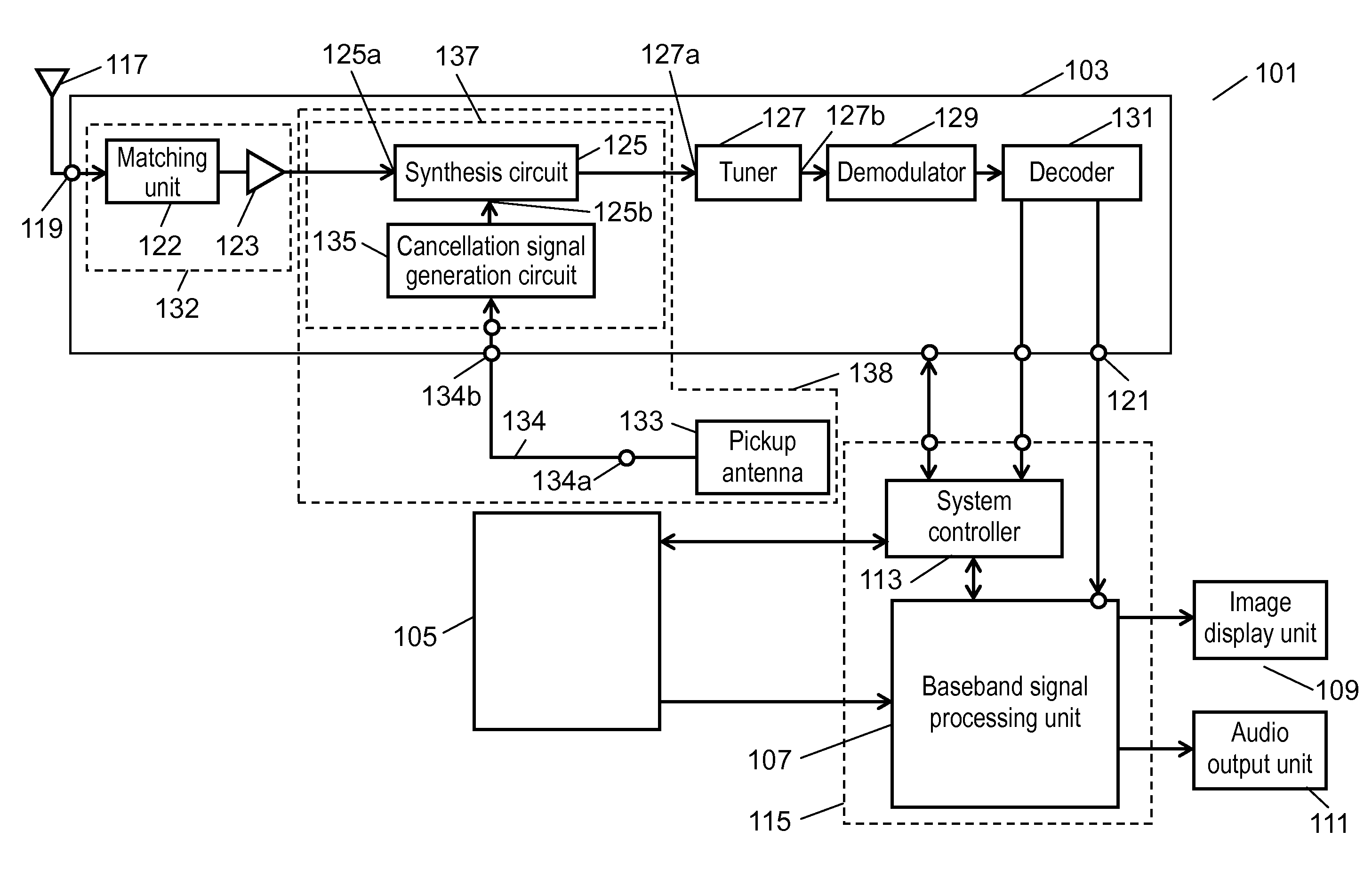
[0035]With reference to FIG. 1, hereinafter, description will be given of a first embodiment of the present invention. FIG. 1 is a block diagram showing a portable device according to the first embodiment of the present invention. In this embodiment, description will be given of portable device 101 capable of receiving a digital television signal in a UHF (Ultra High Frequency) band.
[0036]Portable device 101 includes high-frequency receiver 103 that receives a digital television signal from television signal receiving antenna 117. Portable device 101 also includes main body 105 that has functions as a portable telephone, a portable game machine, a portable computer, a portable electronic dictionary and the like. Portable device 101 also includes baseband signal processing unit 107 to which an output of high-frequency receiver 103 and an output of main body 105 are connected. Portable device 101 also includes image display unit 109 and audio output unit 111 each receiving a signal fr...
second embodiment
[0082]With reference to FIGS. 1, 5A and 5B, hereinafter, description will be given of a second embodiment of the present invention. FIG. 5A is a perspective view showing a lateral side of each block in a portable device according to the second embodiment of the present invention. FIG. 5B is a perspective view showing a top side of each block in the portable device. Portable device 161 according to this embodiment is different from portable device 101 shown in FIGS. 2A and 2B in terms of the following point. That is, in portable device 161, balancing circuits 230a and 230b establish connection between pickup antenna 144 and cancellation signal generation circuit 163. Portable device 161 includes high-frequency receiver 162 to which television signal receiving antenna 117 and pickup antenna 144 are connected. High-frequency receiver 162 is provided with input terminal 231a connected to balancing circuit 230a and input terminal 231b connected to balancing circuit 230b. Herein, pickup a...
third embodiment
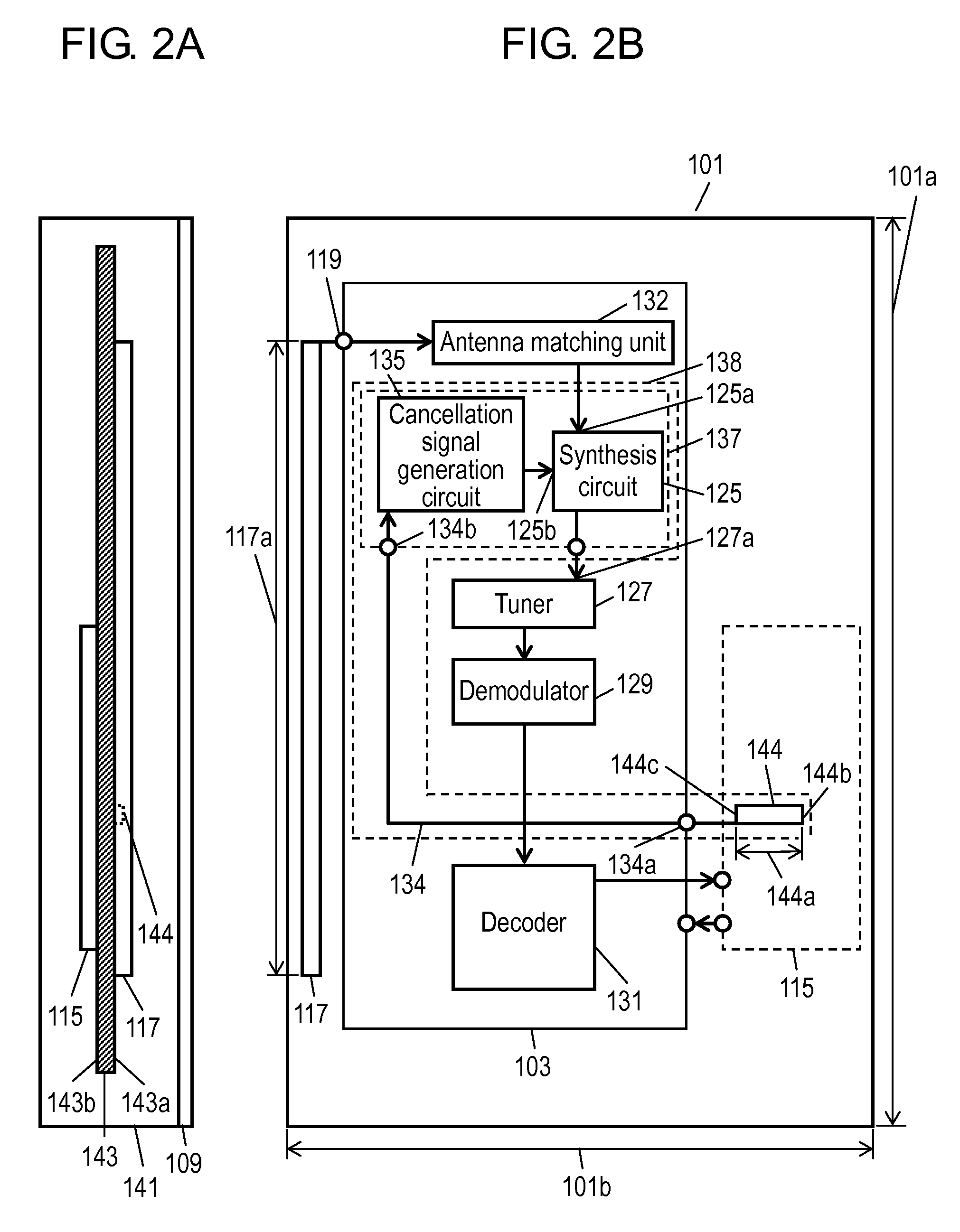
[0088]With reference to FIGS. 1, 6A and 6B, hereinafter, description will be given of a third embodiment of the present invention. FIG. 6A is a perspective view showing a lateral side of each block in a portable device according to the third embodiment of the present invention. FIG. 6B is a perspective view showing a top side of each block in the portable device. Portable device 301 according to this embodiment is different from portable device 101 shown in FIGS. 2A and 2B in terms of the following point. That is, in portable device 301, pickup antenna 144 has first end 144b connected to a ground.
[0089]Portable device 301 includes high-frequency receiver 303 to which television signal receiving antenna 117 and pickup antenna 144 are connected. Herein, pickup antenna 144 and noise cancellation unit 137 form noise canceller 305. First end 144b of pickup antenna 144 is connected to the ground located in proximity to image formation unit 115 serving as a noise signal generation source. ...
PUM
 Abstract
Description
Claims
Application Information
 - R&D
- Intellectual Property
- Life Sciences
- Materials
- Tech Scout
- Unparalleled Data Quality
- Higher Quality Content
- 60% Fewer Hallucinations
Browse by: Latest US Patents, China's latest patents, Technical Efficacy Thesaurus, Application Domain, Technology Topic, Popular Technical Reports.
© 2025 PatSnap. All rights reserved.Legal|Privacy policy|Modern Slavery Act Transparency Statement|Sitemap|About US| Contact US: help@patsnap.com