MIMO antenna apparatus changing antenna elements based on transmission capacity

a technology of transmission capacity and antenna elements, applied in the field of antenna apparatus, can solve the problems of affecting the performance of the mimo demodulation, the inability to achieve the mimo demodulation, and the extremely difficult to improve the mimo demodulation performance, etc., to achieve low electromagnetic coupling, low received power, and small differences

Active Publication Date: 2009-08-06
PANASONIC INTELLECTUAL PROPERTY CORP OF AMERICA
View PDF3 Cites 39 Cited by
  • Summary
  • Abstract
  • Description
  • Claims
  • Application Information

AI Technical Summary

Benefits of technology

[0033]According to typical embodiments of the present invention, briefly speaking, the following effects can be achieved. According to the present invention, it is possible to provide a MIMO antenna apparatus in a small size, capable of maintaining receiving conditions in which radio signals respectively received by a plurality of antenna elements have high received powers, with small differences among the received powers, and with low electromagnetic coupling, thus achieving MIMO communication with high transmission capacity and high transmission quality, and provide a mobile wireless communication apparatus provided with the MIMO antenna apparatus. Specifically, according to the present invention, a wireless communication apparatus is provide

Problems solved by technology

When using the antenna apparatuses disclosed in Patent Documents 1 and 2 as MIMO antenna apparatuses, the following problems arise.
However, in MIMO antenna apparatuses, even when received radio signals have high received powers, if there are large differences among the received powers, a MIMO demodulation result degrades.
Furthermore, in MIMO antenna apparatuses, when the correlation coefficients between antennas are high as much as one, MIMO demodulation cannot be achieved.
That is, in MIMO antenna apparatuses, it is extremely diff

Method used


Image

  • MIMO antenna apparatus changing antenna elements based on transmission capacity
  • MIMO antenna apparatus changing antenna elements based on transmission capacity
  • MIMO antenna apparatus changing antenna elements based on transmission capacity

Examples


Embodiment Construction

[0048]Preferred embodiments of the present invention will be described in detail below with reference to the drawings. Note that components of similar functions are denoted by the same reference numerals throughout the drawings for describing the preferred embodiment of the present invention, and the descriptions thereof are not repeated.

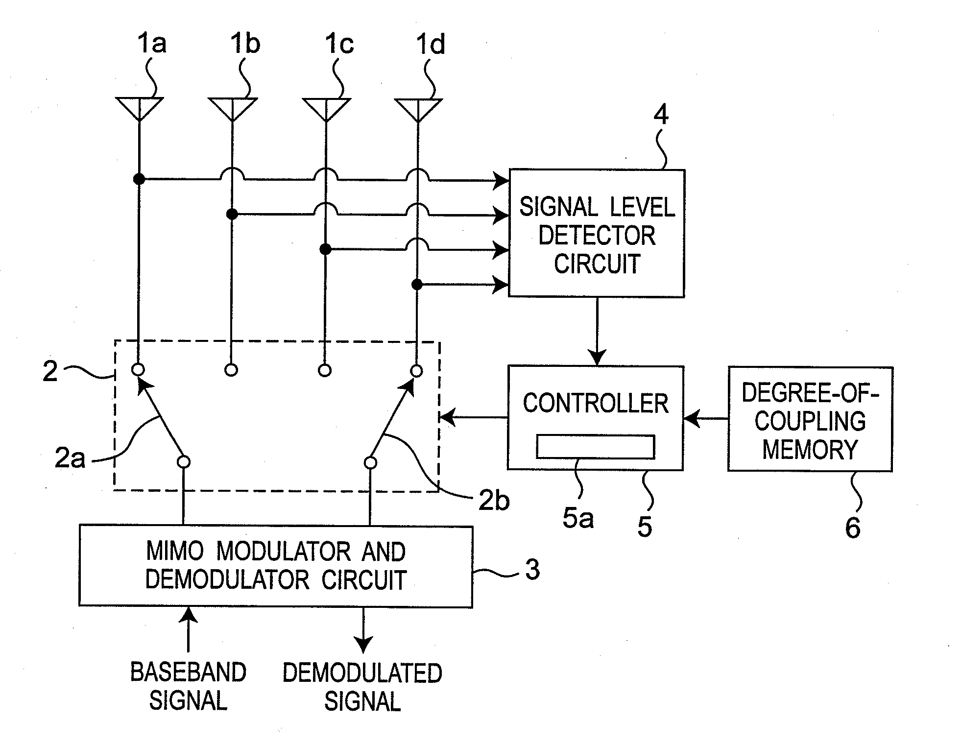
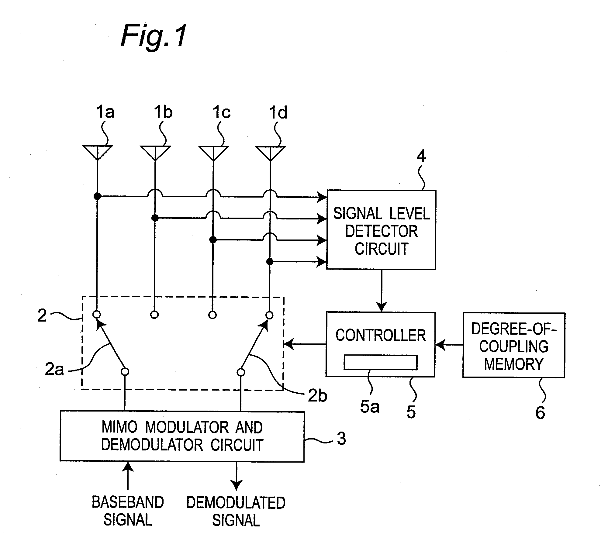
[0049]FIG. 1 is a block diagram showing an exemplary configuration of a MIMO antenna apparatus according to a preferred embodiment of the present invention. With reference to FIG. 1, the MIMO antenna apparatus according to the present preferred embodiment will be described below. Referring to FIG. 1, the MIMO antenna apparatus is provided with four antenna elements 1a, 1b, 1c, and 1d, a switch circuit 2, a MIMO modulator and demodulator circuit 3, a signal level detector circuit 4, a controller 5, and a degree-of-coupling memory 6. The switch circuit 2 includes a switch 2a connected to the antenna elements 1a and 1b and to the MIMO modulator and dem...


PUM


Abstract

A controller of a MIMO antenna apparatus calculates a current transmission capacity based on signal levels detected by a signal level detector circuit. The controller calculates an estimated transmission capacity assuming that at least one of antenna elements currently connected to a MIMO modulator and demodulator circuit is changed to a further antenna element not connected to the MIMO modulator and demodulator circuit, based on the detected signal levels and degrees of electromagnetic coupling stored in a degree-of-coupling memory. The controller controls a switch circuit to connect the further antenna element to the MIMO modulator and demodulator circuit when the current transmission capacity becomes lower than the estimated transmission capacity.

Description

BACKGROUND OF THE INVENTION[0001]1. Field of the Invention[0002]The present invention relates to an antenna apparatus for use in a wireless communication apparatus that operates in mobile communication using a mobile phone, etc. so as to increase communication capacity, achieve high-speed communication, as well as maintain high communication quality. More particularly, the present invention relates to a MIMO antenna apparatus, and a wireless communication apparatus provided with the MIMO antenna apparatus.[0003]2. Description of the Related Art[0004]An antenna apparatus disclosed in Patent Document 1 and an adaptive array wireless apparatus disclosed in Patent Document 2 have been known as antenna apparatuses each using a plurality of antenna elements and selectively changing them (diversity antenna apparatuses).[0005]The antenna apparatus disclosed in Patent Document 1 is provided with an antenna element for transmitting and receiving radio waves. The antenna element has a first fe...

Claims


Application Information

Patent Timeline
IPC IPC(8): H04L1/02
CPCH04B7/0808H04B7/0874H04B7/0831H04B7/0825
Inventor YAMAMOTO, ATSUSHIIWAI, HIROSHISAKATA, TSUTOMUKOYANAGI, YOSHIOHAYASHI, TOSHITERU
Owner PANASONIC INTELLECTUAL PROPERTY CORP OF AMERICA
Why Eureka
Try Eureka