Wind turbine improvements

a technology for wind turbines and wind turbines, which is applied in the direction of rotors, marine propulsion, vessel construction, etc., can solve the problems of difficult source, installation, maintenance, and difficulty of art turbines, so as to reduce downtime, increase the total amount of energy generated, and low cost of generated energy

Inactive Publication Date: 2009-08-06
GREENWARD TECH
View PDF8 Cites 67 Cited by
  • Summary
  • Abstract
  • Description
  • Claims
  • Application Information

AI Technical Summary

Benefits of technology

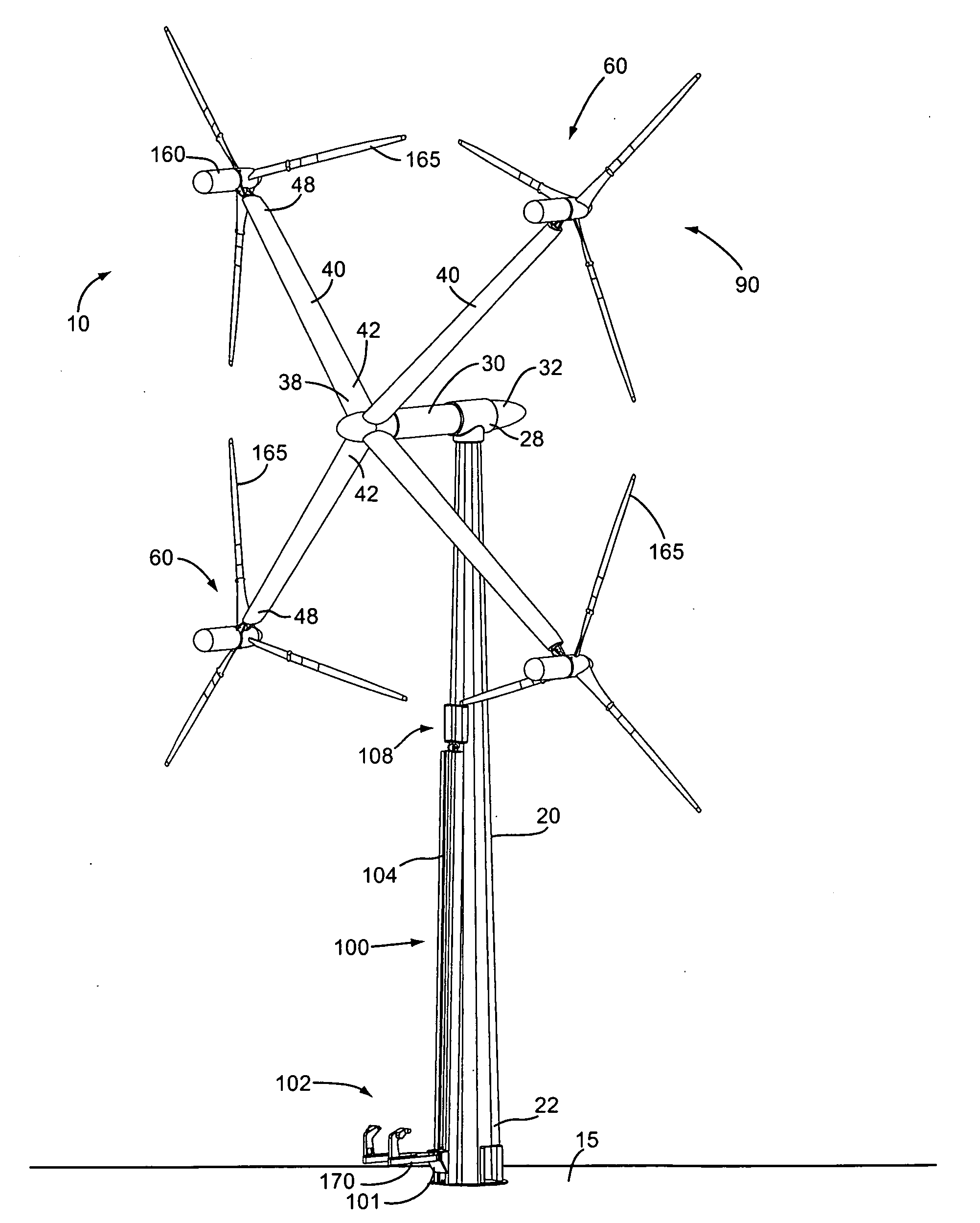
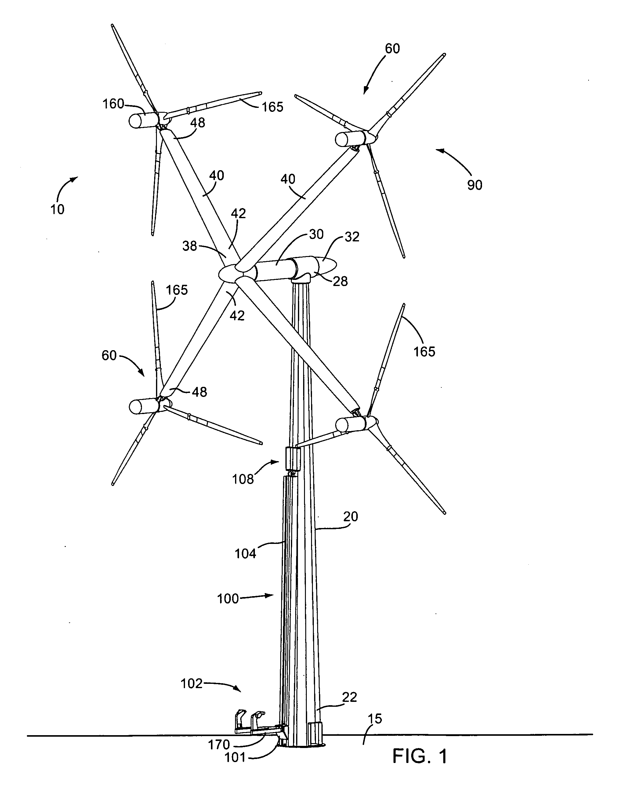
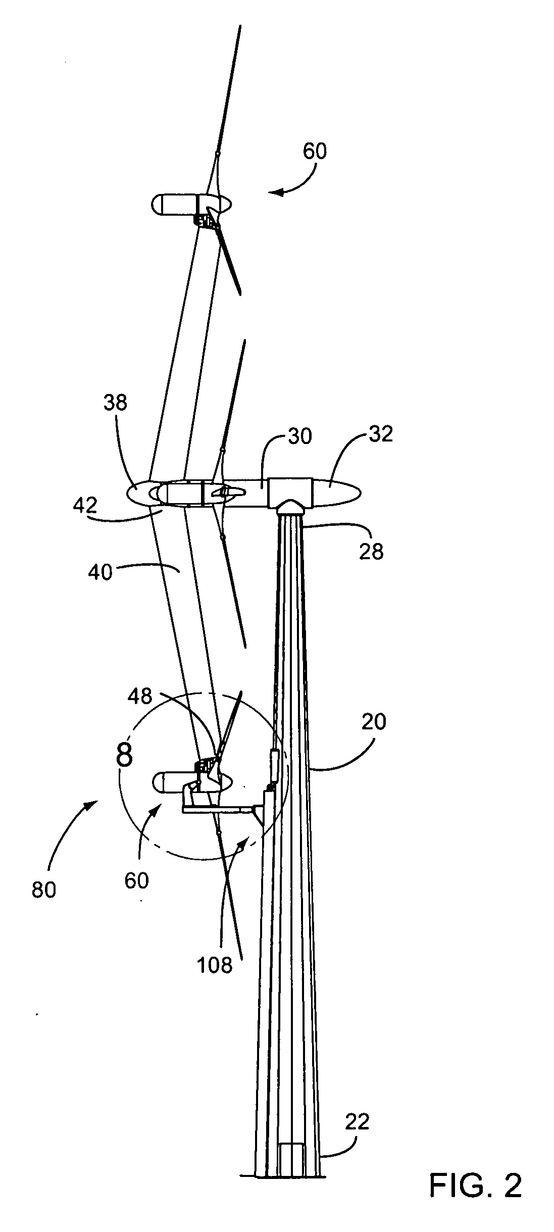
[0015]The tower includes an elevator means adapted to raise and lower one of the turbines between an upper loading position adjacent to a lower loading position of each support arm, and a lower loading position adjacent to the ground surface. In use, each support arm may be rotated to its loading position for receiving one of the turbines thereon. The support arm is then rotated about the hub into an operating position. In the preferred embodiment, the hub is positioned about the tower such that each turbine is upwind of the tower. As such, each turbine is able to operate with minimal turbulent effect from the tower and aerodynamically-shaped support arms.
[0017]The present device provides for the use of multiple mid-size, lightweight, modular wind turbines in counter-rotating arrays that can be oriented to face a changing wind direction. The present invention results in a relatively low cost for generated energy, and provides for reduced downtime—and consequent lost revenue due to major mechanical or electrical failures—by allowing rapid replacement of wind turbine modules. The present arrangement provides means to raise and lower turbine modules, thereby eliminating the need for large cranes when performing maintenance. The instant invention increases the total amount of energy generated per acre of wind resource, and improves supply chain economics due to the smaller size of the individual components and increased component order quantities. Other features and advantages of the present invention will become apparent from the following more detailed description, taken in conjunction with the accompanying drawings, which illustrate, by way of example, the principles of the invention.

Problems solved by technology

Such a prior art turbine, however, is difficult to source, install, and maintain.

Method used


Image

  • Wind turbine improvements
  • Wind turbine improvements
  • Wind turbine improvements

Examples


Embodiment Construction

[0030]Illustrative embodiments of the invention are described below. The following explanation provides specific details for a thorough understanding of and enabling description for these embodiments. One skilled in the art will understand that the invention may be practiced without such details. In other instances, well-known structures and functions have not been shown or described in detail to avoid unnecessarily obscuring the description of the embodiments.

[0031]Unless the context clearly requires otherwise, throughout the description and the claims, the words “comprise,”“comprising,” and the like are to be construed in an inclusive sense as opposed to an exclusive or exhaustive sense; that is to say, in the sense of “including, but not limited to.” Words using the singular or plural number also include the plural or singular number respectively. Additionally, the words “herein,”“above,”“below” and words of similar import, when used in this application, shall refer to this appli...


PUM


Abstract

A wind turbine arrangement is disclosed that includes a substantially vertical tower mounted to a ground surface, a horizontally-extending hub rotatably fixed in a substantially horizontal plane to an upper end of the tower, at least one radial support arm rotatably fixed with a distal end of the hub, each support arm including a turbine mounting means at a distal end thereof, and at least one electricity-generating turbine selectively mountable with the turbine mounting means of the any of the support arms. An elevator means adapted to raise and lower each of the turbines between an upper loading position adjacent to a lower loading position of each support arm, and a lower loading position adjacent to the ground surface. In use, each support arm may be rotated to the loading position for receiving one of the turbines thereon. The support arm is then rotated about the hub into an operating position.

Description

CROSS-REFERENCE TO RELATED APPLICATIONS[0001]This application claims the benefit of U.S. Provisional Patent Application 61 / 063,711, filed on Feb. 5, 2008, and incorporated herein by reference.STATEMENT REGARDING FEDERALLY SPONSORED RESEARCH AND DEVELOPMENT[0002]Not Applicable.NOTICE OF COPYRIGHTS AND TRADE DRESS[0003]A portion of the disclosure of this patent document contains material which is subject to copyright protection. This patent document may show and / or describe matter which is or may become trade dress of the owner. The copyright and trade dress owner has no objection to the facsimile reproduction by any one of the patent disclosure as it appears in the Patent and Trademark Office patent files or records, but otherwise reserves all copyright and trade dress rights whatsoever.FIELD OF THE INVENTION[0004]This invention relates to wind turbines, and more particularly to an improved wind turbine configuration.DISCUSSION OF RELATED ART[0005]Development of wind energy conversio...

Claims


Application Information

Patent Timeline
Patent Type & Authority Applications(United States)
IPC IPC(8): F03D1/02F03D11/04
CPCF03D1/001F03D1/003F03D1/02Y02E10/728F05B2240/34F05B2240/916Y02E10/721F03D11/04F03D13/10F03D13/20F03D80/50F05B2240/374Y02E10/72F03D80/85F03D80/88
Inventor SALTER, EDMUND
Owner GREENWARD TECH
Why Eureka
Try Eureka