Bone prosthesis

a bone prosthesis and bone technology, applied in the field of bone prosthesis, can solve the problems of uneven wear of the ankle, loss of mobility of the ankle, cartilage erosion and subsequent break down of the subchondral bone,

Inactive Publication Date: 2009-08-06
TALUS MEDICAL
View PDF50 Cites 60 Cited by
  • Summary
  • Abstract
  • Description
  • Claims
  • Application Information

AI Technical Summary

Problems solved by technology

Osteoarthritis or trauma can result in ankle pathology of uneven wear on, and/or direct trauma to, the surface of the talus.
This commonly leads to cartilage erosion and subsequent break down of subchondral bone.
This fusion

Method used


Image

  • Bone prosthesis
  • Bone prosthesis
  • Bone prosthesis

Examples


Embodiment Construction

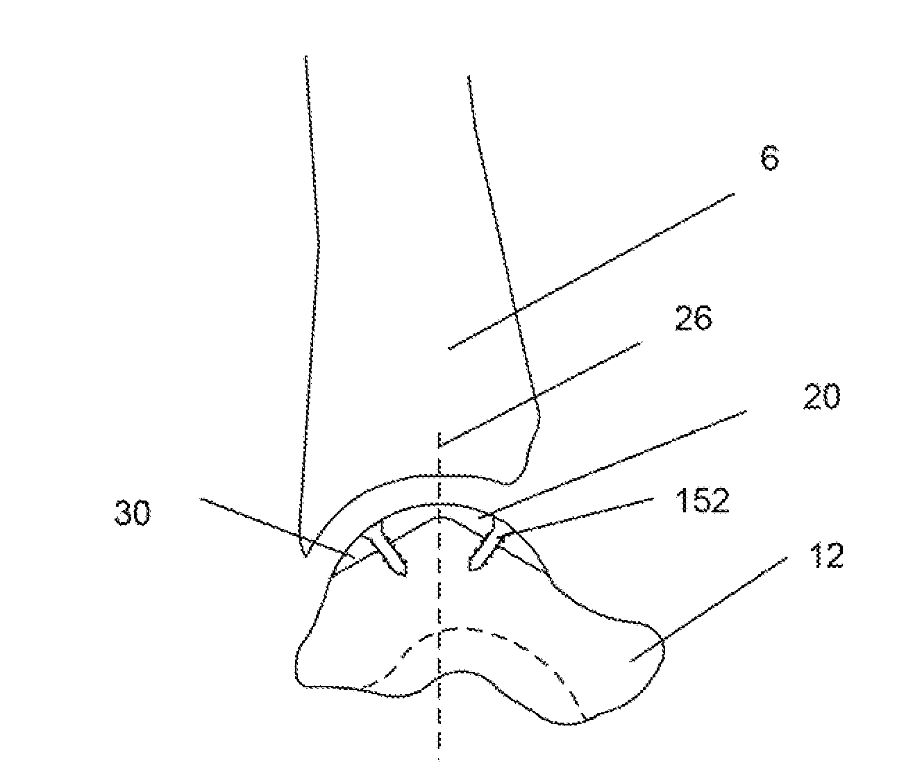
[0054]FIG. 7 illustrates that the partial bone prosthesis can have a prosthesis body 24. The prosthesis body 24 can have a central axis 26. During use in a long bone, the central axis 26 can be substantially parallel and / or aligned with a longitudinal axis of the long bone. During use in the talus 12 or in a vertebra, the central axis 26 can be substantially parallel and / or aligned with a vertical axis 8.

[0055]The prosthesis body 24 can have a central portion 28. The central axis 26 can pass through the central portion 28. The prosthesis body 24 can have a perimeter anchor 30. The perimeter anchor 30 can be radially distal to the central axis 26. The perimeter anchor 30 can partially or completely surround the central portion 28.

[0056]The prosthesis can have a distal prosthesis surface 32. The distal prosthesis surface 32 can be configured to substantially match the exterior of the portion of the bone being replaced by the prosthesis. The proximal and distal prosthesis surfaces 32 a...


PUM

PropertyMeasurementUnit
Fractionaaaaaaaaaa
Fractionaaaaaaaaaa
Perimeteraaaaaaaaaa

Abstract

A partial bone prosthesis and methods of using the same are disclosed herein. The partial bone prosthesis can be configured for use, for example, on the superior side of the talus or an end of a long bone, such as the tibia. The partial bone prosthesis can anchor to the perimeter of the contact patch between the bone and the prosthesis. For example, the prosthesis can be attached to the talus without drilling holes through the talus, preserving structural integrity and blood flow within the talus.

Description

CROSS-REFERENCE TO RELATED APPLICATIONS[0001]This application is a continuation of PCT International Application No. PCT / US2007 / 063233 filed Mar. 2, 2007 which claimed benefit of priority to U.S. Provisional Application No. 60 / 779,307 filed Mar. 2, 2006, both of which are incorporated by reference herewith in their entirety.FIELD OF THE INVENTION[0002]This invention relates to a bone prosthesis and methods of using the same. More specifically, the bone prosthesis can be anchored perimeterly.BACKGROUND OF THE INVENTION[0003]Osteoarthritis or trauma can result in ankle pathology of uneven wear on, and / or direct trauma to, the surface of the talus. This commonly leads to cartilage erosion and subsequent break down of subchondral bone. Osteoarthritis and certain trauma on the talus are often treated by fusing the talus to the tibia. This fusion procedure results in loss of mobility of the ankle, and the expected complications resulting from a loss of mobility including gait changes, fur...

Claims


Application Information

Patent Timeline
IPC IPC(8): A61F2/42
CPCA61B17/06166A61F2310/00359A61B17/86A61F2/28A61F2/30721A61F2/32A61F2/34A61F2/36A61F2/3607A61F2/38A61F2/3804A61F2/3859A61F2/389A61F2/40A61F2/4081A61F2/4202A61F2/44A61F2002/2817A61F2002/30062A61F2002/30065A61F2002/3008A61F2002/30082A61F2002/30092A61F2002/3039A61F2002/30574A61F2002/30578A61F2002/30685A61F2002/30754A61F2002/30787A61F2002/3082A61F2002/30884A61F2002/30904A61F2002/4011A61F2002/4018A61F2002/4205A61F2002/4207A61F2210/0004A61F2210/0014A61F2210/0071A61F2210/0095A61F2220/0025A61F2250/0098A61F2310/00017A61F2310/00023A61F2310/00029A61F2310/00047A61F2310/00071A61F2310/00101A61F2310/00137A61F2310/00365A61F2310/00796A61B17/68
Inventor CHOI, GEORGE Y.WARNE, JAMES BRIAN
Owner TALUS MEDICAL
Why Eureka
Try Eureka