Decoupler devices to prevent backdrive in air turbine starters

a technology of air turbine starter and decoupler device, which is applied in the direction of couplings, machines/engines, mechanical equipment, etc., can solve the problems of transmitting reverse torque and backdriving the air turbine starter, the conventional decoupler device may suffer from one or more shortcomings, and the overrunning can continue to occur, etc., to achieve the effect of reducing friction and reducing friction

Active Publication Date: 2009-08-13
HONEYWELL INT INC
View PDF8 Cites 35 Cited by
  • Summary
  • Abstract
  • Description
  • Claims
  • Application Information

AI Technical Summary

Benefits of technology

[0006]In accordance with another exemplary embodiment, a decoupler device is provided for decoupling an output member of a starter from an engine. The decoupler device includes a first shaft portion configured to be coupled to and rotate with the output member; a second shaft portion configured to be coupled to and rotate with the engine, the first and second shaft portions being axially aligned and configured to engage each another for rotation in a first direction and to separate from each other in a second direction to decouple the output member from the engine; and a bearing arranged between the output member and the second shaft portion for reducing friction between the second shaft portion and the output member when the first and second shaft portions are decoupled.
[0007]In accordance with yet another exemplary embodiment, an air turbine starter is provided for starting an engine. The starter includes a housing defining an inlet, an outlet, and a flow path extending between the inlet and the outlet for communicating a flow of gas therethrough; a turbine member journaled within the housing and disposed withi

Problems solved by technology

Such overrunning can occur continuously during operation of the turbine engine.
In some instances, if problems with the clutch occur, the clutch may transmit reverse torque and backdrive the air turbine starter.
Unfortunately, a conventional decoupler device may suffer from one or more shortcomings.
The conventional decoupler device may be overly large or complex in its construction, can provide a possible source of malfunction or breakdown

Method used


Image

  • Decoupler devices to prevent backdrive in air turbine starters
  • Decoupler devices to prevent backdrive in air turbine starters
  • Decoupler devices to prevent backdrive in air turbine starters

Examples


Embodiment Construction

[0014]The following detailed description is merely exemplary in nature and is not intended to limit the invention or the application and uses of the invention. Furthermore, there is no intention to be bound by any theory presented in the preceding background or the following detailed description.

[0015]Broadly, exemplary embodiments described herein provide decoupler devices in starters for engines, typically for aircraft. The decoupler devices function to decouple the starter from the engine during a failure event. Particular exemplary embodiments provide a bearing structure that reduces wear between the decoupler device and other portions of the starter. The bearing structures can include, for example, wear coatings, bushings, ball bearings, and roller bearings.

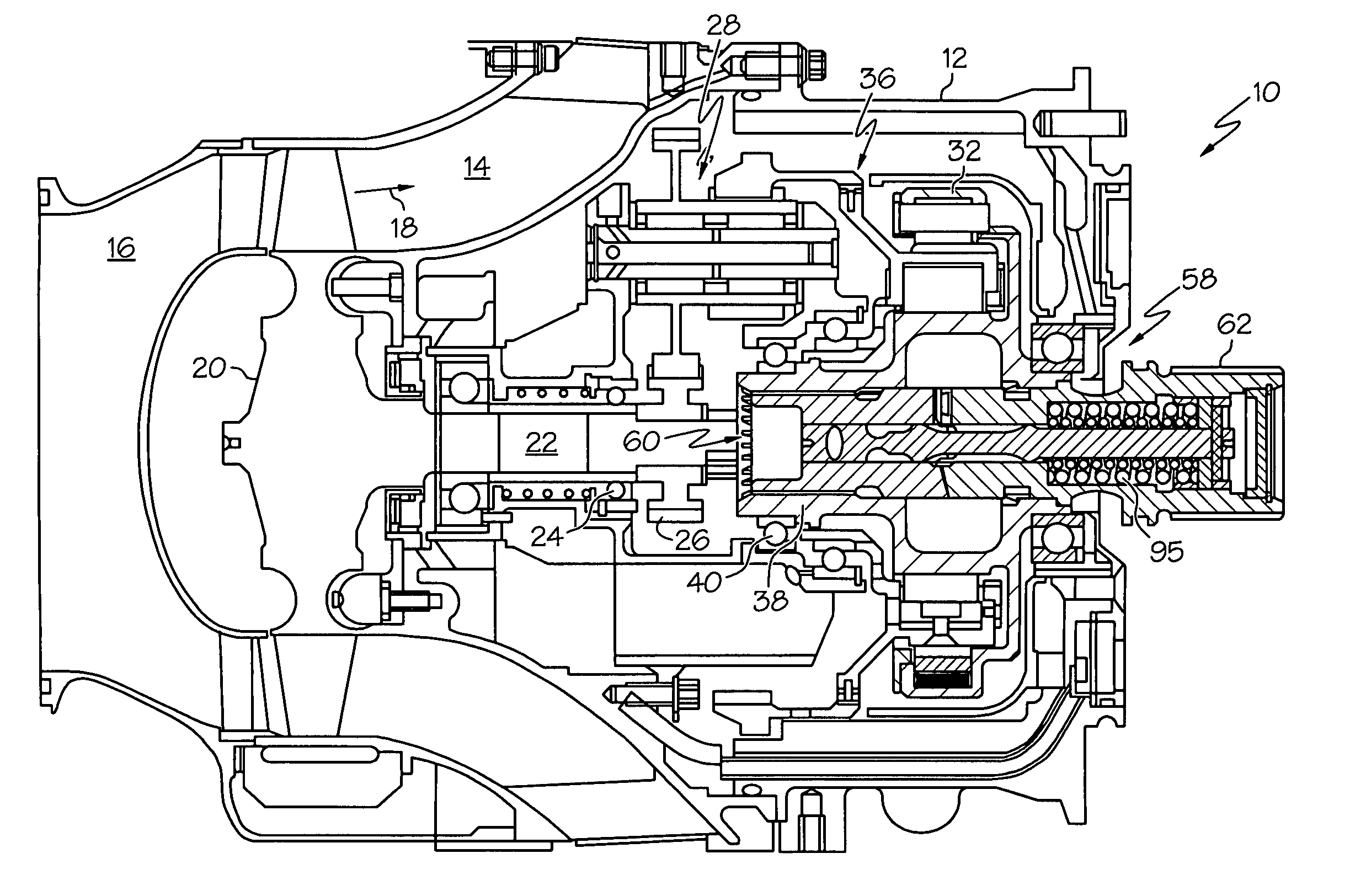
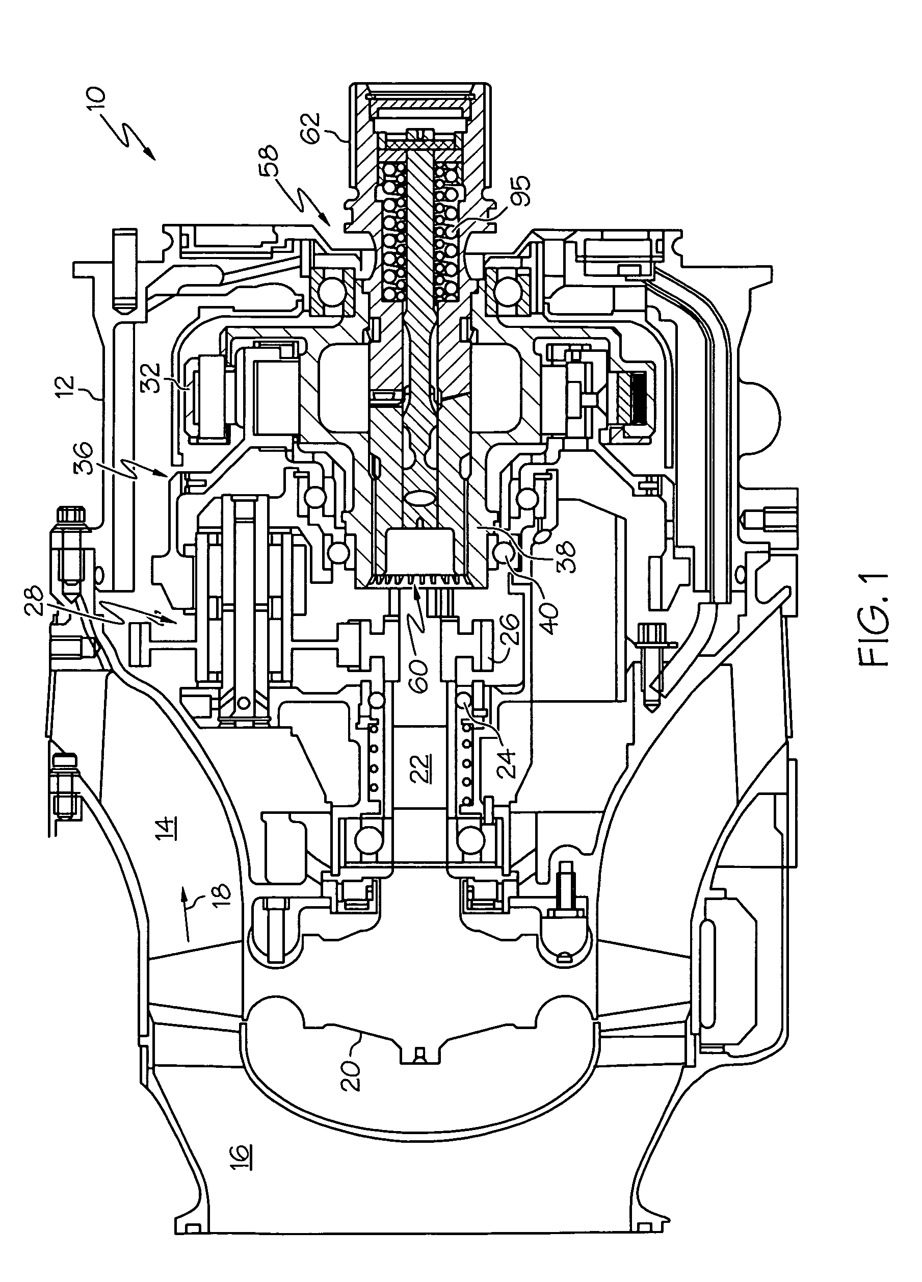
[0016]FIG. 1 depicts a cross-sectional view of an exemplary air turbine starter 10. The air turbine starter 10 includes a housing 12 defining an inlet 16 and an outlet 14. The housing 12 further defines a flow path 18 extend...


PUM


Abstract

An air turbine starter for starting an engine includes a housing, and a flow path communicating a flow of gas therethrough; a turbine member; a clutch; and a decoupler device at least partially housed within the output member of the clutch. The decoupler device includes a first shaft portion coupled to and rotating with the output member and a second shaft portion coupled to and rotating with the engine. The first and second shaft portions are axially aligned and configured to engage each another for rotation in a first direction and to separate from each other in a second direction to decouple the output member of the clutch from the engine. The starter further includes a bearing between the inner surface of the output member and the second shaft portion for reducing friction between the second shaft portion and the inner surface of the output member when the first and second shaft portions are decoupled.

Description

TECHNICAL FIELD[0001]The present invention generally relates to decoupler devices of air turbine starters capable of driving in one direction only, and decoupling in response to a specific torque load in the opposite direction.BACKGROUND[0002]Air turbine starters are known in the aviation field, and are commonly used to start propulsion turbine engines of modern aircraft. A starter typically includes a clutch that overruns when the turbine engine achieves a certain operating speed. Such overrunning can occur continuously during operation of the turbine engine. In some instances, if problems with the clutch occur, the clutch may transmit reverse torque and backdrive the air turbine starter. To prevent undesirable backdriving of the starter by the turbine engine, a decoupler device is conventionally provided in the power train between the starter and turbine engine.[0003]Unfortunately, a conventional decoupler device may suffer from one or more shortcomings. The conventional decoupler...

Claims


Application Information

Patent Timeline
IPC IPC(8): F02C7/275F16D9/00
CPCF02C7/275F02C7/32F05D2260/52F05D2260/4023F05D2260/85F02C7/36F02C7/277
Inventor GOCKEL, RICHOMAN, DAVIDKUMAR, ARUNSMITH, DOUGSILK, JOEHO, BEN
Owner HONEYWELL INT INC
Why Eureka
Try Eureka