Gas sensor

a technology of gas sensor and ecu, which is applied in the field of gas sensor, can solve the problems of limiting the degree of freedom of design of ecu, restricting the mode of use of ecu, and consuming time in layout study, so as to improve the degree of freedom of design and versatility of ecu, and be less susceptible to electric noise

Inactive Publication Date: 2009-08-13
NGK SPARK PLUG CO LTD
View PDF13 Cites 14 Cited by
  • Summary
  • Abstract
  • Description
  • Claims
  • Application Information

AI Technical Summary

Benefits of technology

[0006]The present invention has been conceived in view of the above-mentioned conventional circumstances. An object of the invention is to

Problems solved by technology

This involves a problem of limiting the degree of freedom of design of the ECU and a problem of restricting the mode of use of the ECU.
Particularly, in the case where a large number of components are to be mounted in the ECU, difficulty is encountered in securing an installation space for the processing means associated with the oxygen sensor, so that time is consumed in study of layout.
Also, since the sensor si

Method used


Image

  • Gas sensor
  • Gas sensor
  • Gas sensor

Examples


Embodiment Construction

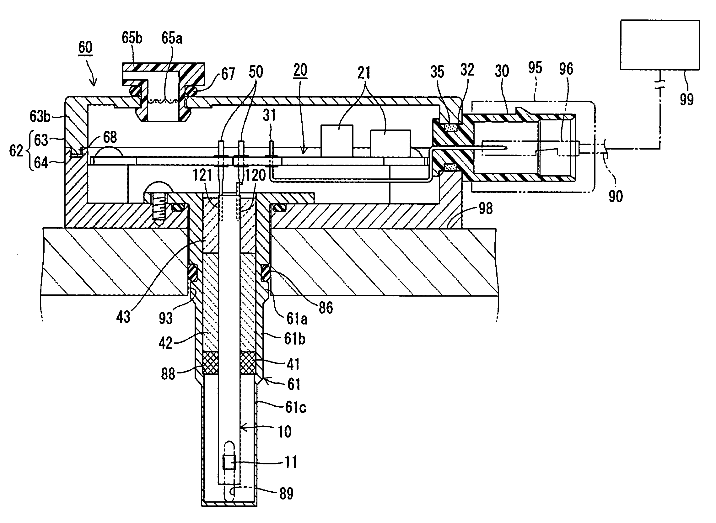
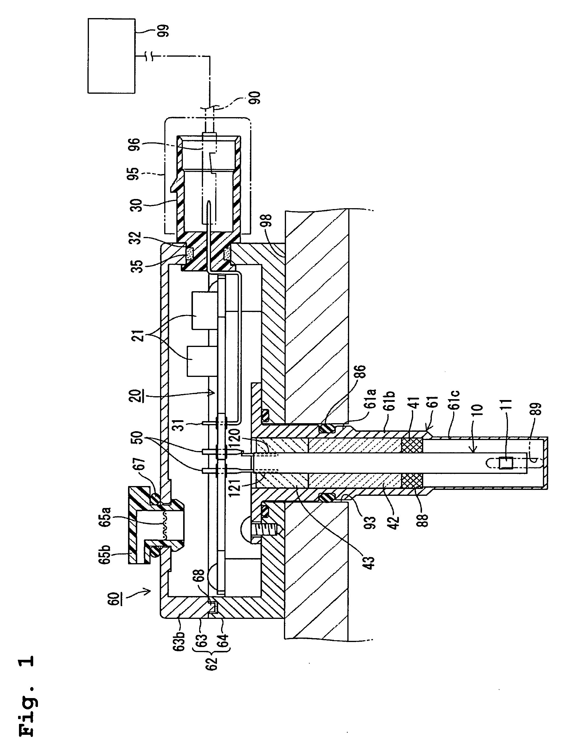
[0037]A gas sensor according to an embodiment of the present invention will next be described in detail with reference to the drawings. As shown in FIG. 1, the gas sensor includes a sensor element 10, a circuit board 20, terminals 50, and a casing 60, which collectively houses the components.

[0038]The sensor element 10 assumes the form of a plate extending in the longitudinal direction thereof and has a detecting portion 11 formed at a forward end (on a first-end side with respect to the longitudinal direction; specifically, on a side toward its lower end in FIG. 1) and electrode terminal portions 120 and 121 formed on front and back surfaces of the sensor element 10 at the upper end thereof.

[0039]As shown in FIG. 8, the sensor element 10 has a structure in which a detection element 300 and a heater 200 are laminated together. The detection element 300 has a structure in which an oxygen-concentration detection cell 130 and an oxygen pump cell 140 are laminated together.

[0040]The hea...


PUM


Abstract

A gas sensor includes a plate-like sensor element having solid electrolyte layers; a circuit board having a processing circuit for processing an output signal from the sensor element; terminals connected to the sensor element and to the circuit board and serving as electric junctions therebetween; and a metallic casing which encloses the sensor element, the circuit board, and the terminals and has attachment portions for attachment to an external object. The attachment portions are attached to an inlet pipe at a position located downstream of an EGR gas inlet or to a cylinder head.

Description

FIELD OF THE INVENTION[0001]The present invention relates to a gas sensor.BACKGROUND OF THE INVENTION[0002]Japanese Patent Application Laid-Open (kokai) No. 2007-139749) discloses a gas sensor disposed in an exhaust path of an automobile engine that is adapted to detect the concentration of oxygen contained in exhaust gas for utilization in combustion control of the engine. The oxygen sensor includes a tubular metallic shell and a plate-like sensor element, which is held in the metallic shell. The sensor element has a structure in which a detection element having solid electrolyte layers and electrodes and a heater having a heat-generating element and electrodes are laminated together. The sensor element extends in its longitudinal direction and has a detecting portion provided at its one longitudinal end region for exposure to a gas-to-be-measured. An electrode terminal portion is provided at its other longitudinal end region for electrical connections through electrodes and lead p...

Claims


Application Information

Patent Timeline
IPC IPC(8): G01N27/26
CPCG01N27/407G01N27/4062
Inventor YOSHIKAWA, TAKAYAKONDO, MASARUISOMURA, HIROSHINISHIO, HISAHARUTAJIMA, TOMOHIRO
Owner NGK SPARK PLUG CO LTD
Why Eureka
Try Eureka