Method for compensating for angular transmission error of an actuator

a technology of angular transmission error and actuator, which is applied in the field of actuator, can solve the problems of poor reproducibility of fs-wg relative-rotation synchronized component (mobile component), angular transmission error degrades the positioning response of actuator, and no effective method is proposed for compensating non-linear elastic deformation components. achieve the effect of improving positioning precision

Active Publication Date: 2009-08-13
NAGOYA INSTITUTE OF TECHNOLOGY
View PDF3 Cites 13 Cited by
  • Summary
  • Abstract
  • Description
  • Claims
  • Application Information

AI Technical Summary

Benefits of technology

[0011]In light of these problems, it is an object of the present invention to propose a method for compensating for angular transmission error of an actuator, the method being capable of effectively eliminating or minimizing the non-linear elastic deformation component included in the angular transmission error of an actuator provided with a wave gear drive.
[0012]It is also an object of the present invention to add compensation for the non-linear elastic deformation component to current angular transmission error compensation, thereby providing a method for compensating for angular transmission error of an actuator capable of further improving positioning precision.
[0013]The non-linear elastic deformation component included in the angular transmission error of an actuator provided with a wave gear drive is a component of the angular transmission error occurring due to elastic deformation of the flexible externally-toothed gear when the direction of rotation of the motor changes, and can be analyzed by driving the motor in a sine-wave shape manner. A model of the non-linear elastic deformation component (non-linear model) obtained from the analysis results is used in the present invention to store data or a function for compensating for this component in a motor-control device. Compensation for the non-linear elastic deformation component (θHys) is added to a motor-shaft angle command (θ*M) as a compensation input (Nθ*TE) for feed-forward compensation. As a result, according to the present invention, the non-linear elastic deformation component (θHys) can be effectively reduced, and the positioning precision of the actuator can be improved.
[0024]According to the method for compensating for angular transmission error of the present invention, a model of a non-linear elastic deformation component is used to compensate for angular transmission error that is pronounced when the direction of positioning changes due to the occurrence of overshoot or the like, whereby positioning precision can be improved relative to the prior art, even when overshoot occurs.

Problems solved by technology

Angular transmission error degrades the positioning response of an actuator provided with a wave gear drive.
The angular transmission error of an actuator provided with a wave gear drive includes a non-linear elastic deformation component that is not synchronized to rotation and that occurs due to elastic deformation of the flexible externally-toothed gear of the wave gear drive.
However, an effective method was not proposed for compensating for the non-linear elastic deformation component that is not synchronized to rotation and that occurs due to elastic deformation of the flexible externally-toothed gear.
Measurement results for the FS-WG relative-rotation synchronized component (mobile component) have poor reproducibility.
Therefore, compensation cannot be performed for the FS-WG relative-rotation synchronized component (mobile component) and the load-shaft synchronized component.

Method used


Image

  • Method for compensating for angular transmission error of an actuator
  • Method for compensating for angular transmission error of an actuator
  • Method for compensating for angular transmission error of an actuator

Examples


examples

Experimental Method

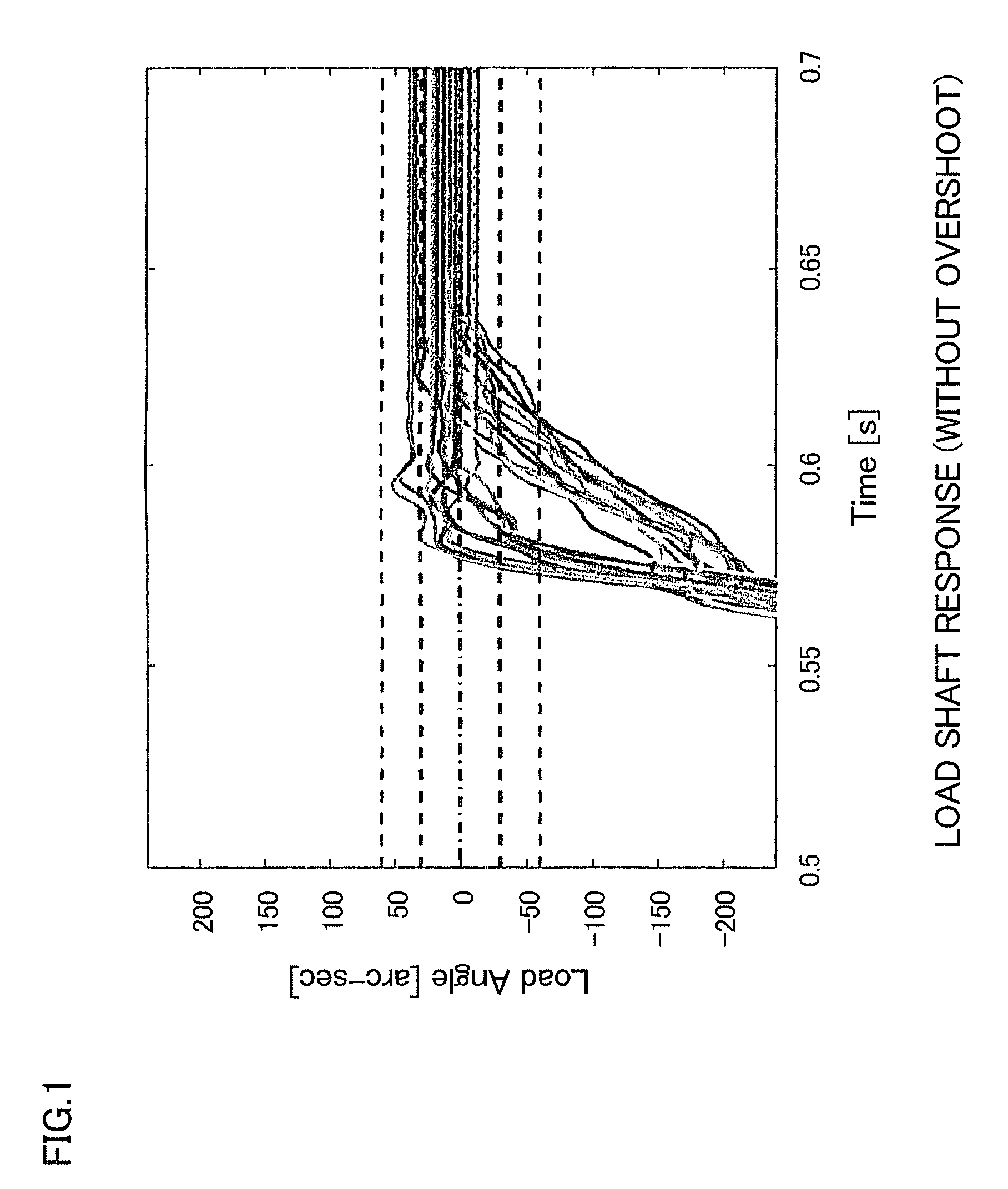
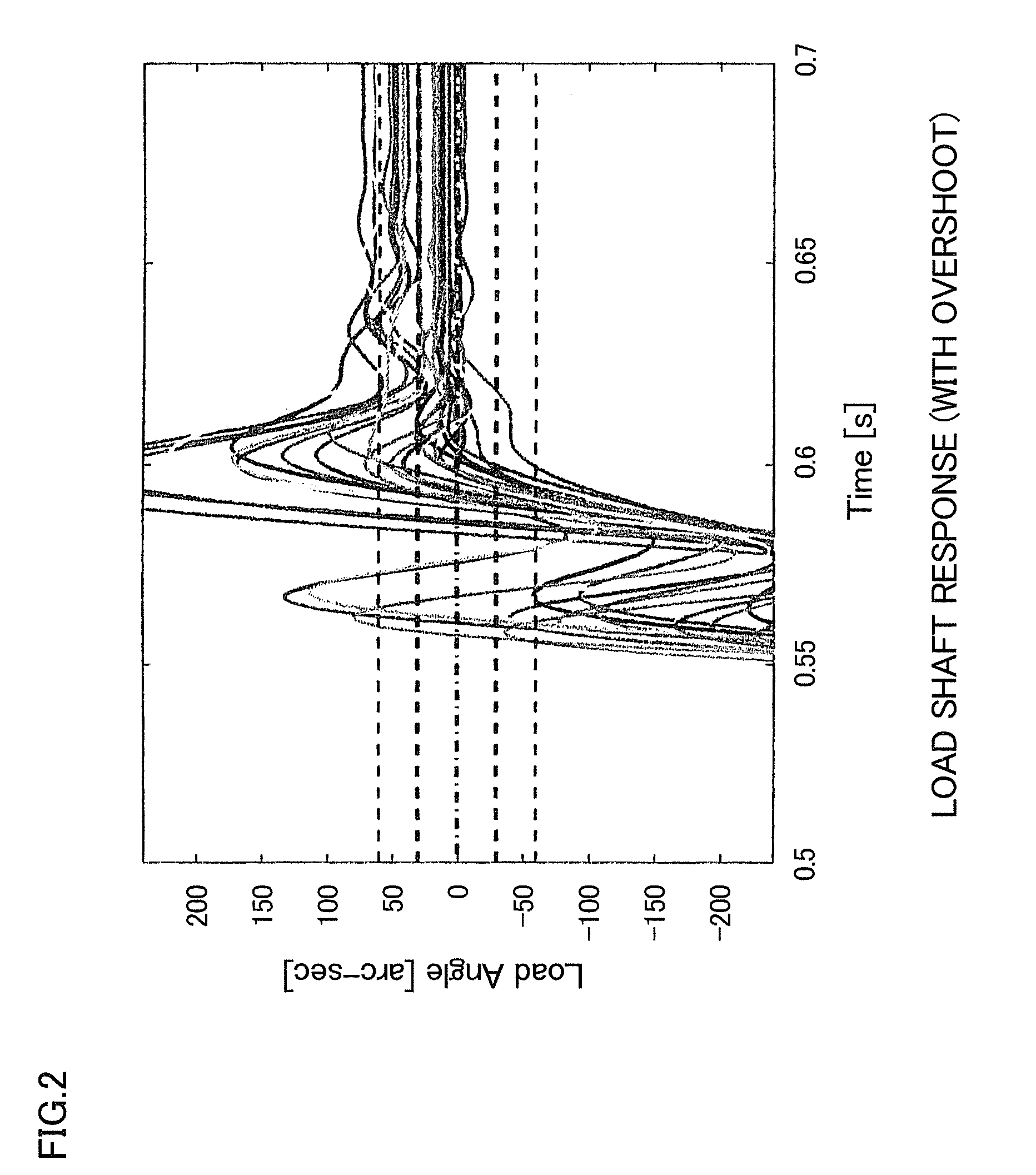
[0056]Compensation for the non-linear elastic deformation component was performed in order to reduce the dispersion in the angle of the load shaft (the actuator output shaft) when overshoot occurs during the indexing operation of a dividing plate or the like. Tables 2, 3, and 4 show, respectively, the experimental conditions, the conditions for compensating for angular transmission error, and the parameters for the model of the non-linear elastic deformation component. The Mid model (the alternatingly-dotted line in FIG. 9) was used for compensation of the motor-shaft synchronized component (fixed component). The model Mid comprises the average values of the counterclockwise model and the clockwise model of the motor-shaft synchronized component (fixed component) measured when causing the motor to rotate in the clockwise direction and in the counterclockwise direction.

TABLE 2Experimental conditionsControl systemP-PI control system + bang-bang controlOperation patt...


PUM


Abstract

The non-linear elastic deformation component included in the angular transmission error of an actuator provided with a wave gear drive is a component of the angular transmission error occurring due to elastic deformation of a flexible externally-toothed gear when the direction of rotation of the motor shaft changes. This component can be analyzed by driving the motor in a sine-wave shape. A model of the non-linear elastic deformation component (non-linear model) obtained from the analysis results is used to store data or a function for compensating for this component in a motor-control device. Compensation for the non-linear elastic deformation component (θHys) is added to a motor-shaft angle command (θ*M) as a compensation input (Nθ*TE) for feed-forward compensation. As a result, the non-linear elastic deformation component (θHys) can be effectively reduced, and the positioning precision of the actuator can be improved.

Description

BACKGROUND OF THE INVENTION[0001]1. Field of the Invention[0002]The present invention relates to an actuator configured so that output rotation of a motor is reduced in speed and output via a wave gear drive. The present invention more specifically relates to a method for compensating for angular transmission error of an actuator, the method being capable of eliminating or reducing an angular transmission error component (a non-linear elastic deformation component) resulting from elastic deformation of a flexible externally-toothed gear of the wave gear drive.[0003]2. Description of the Related Art[0004](Current State of Angular Transmission Error Compensation for an Actuator Provided with a Wave Gear Drive)[0005]Angular transmission error degrades the positioning response of an actuator provided with a wave gear drive. The components of this angular transmission error in the prior art are a motor-shaft synchronized component (fixed component), which is synchronized to the rotation ...

Claims


Application Information

Patent Timeline
Patent Type & Authority Applications(United States)
IPC IPC(8): G05B11/01F16H1/32G05B13/02G05B13/04G05D3/12H02P29/00
CPCG05B19/404G05B2219/41358G05B2219/41148G05B2219/41032
Inventor SASAKI, KOZOOKITSU, YOSHIFUMIYAJIMA, TOSHIOIWASAKI, MAKOTO
Owner NAGOYA INSTITUTE OF TECHNOLOGY
Why Eureka
Try Eureka