
Voltage regulator with compensation and the method thereof

a voltage regulator and compensation technology, applied in the field of compensation for voltage regulators, can solve the problems of large compensating capacitance, large compensating capacitance, and load capacitance seen by a circuit having compensating capacitance, etc., to achieve the effect of occupying more physical space and occupying more spa

Inactive Publication Date: 2009-08-13
MEDIATEK INC
View PDF4 Cites 4 Cited by
  • Summary
  • Abstract
  • Description
  • Claims
  • Application Information

AI Technical Summary

Benefits of technology

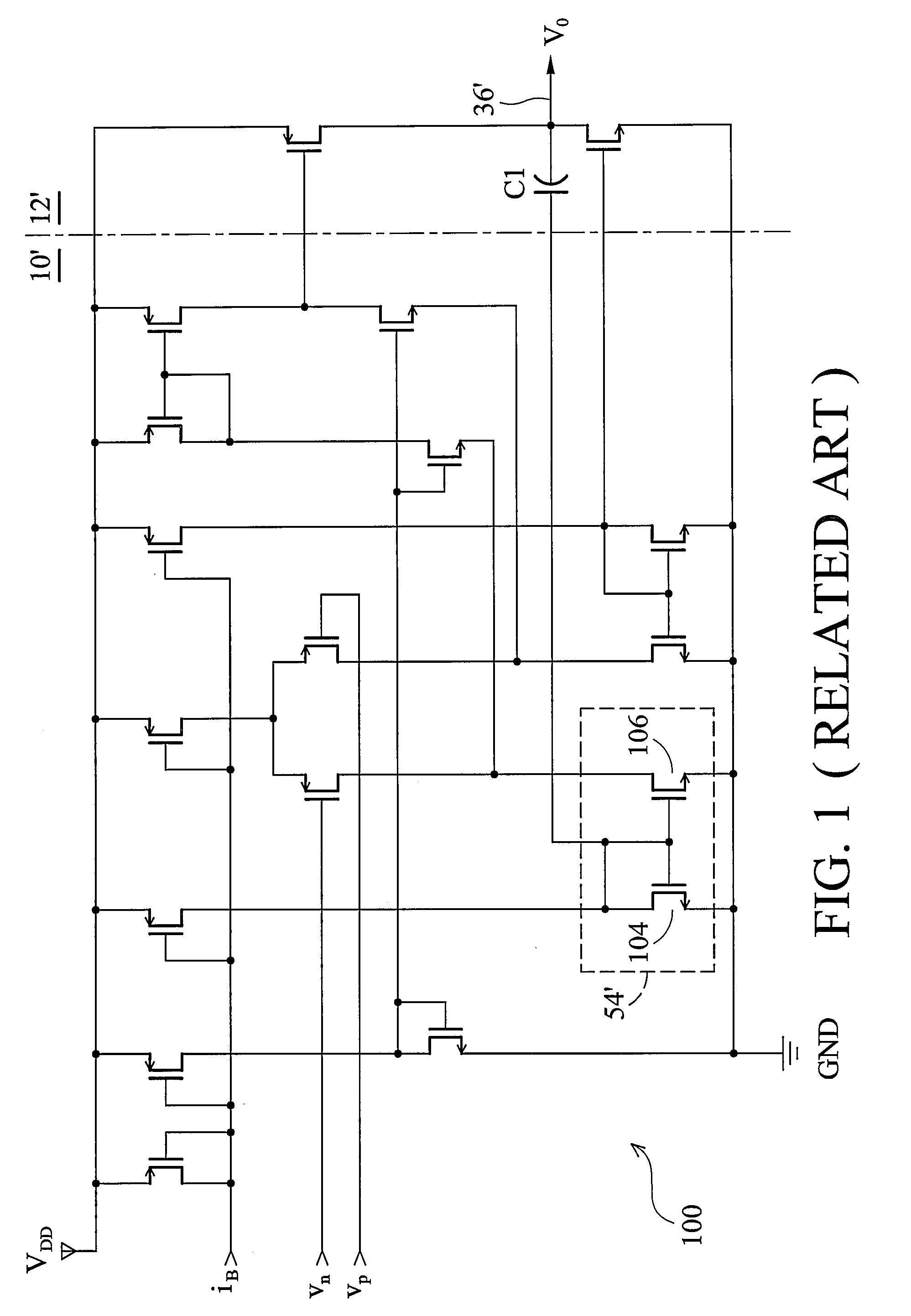
[0004]The stability of performance of circuits having feedback is improved by providing compensation so as to increase phase margin. A well known technique for improving phase margin takes advantage of the Miller Effect, by adding a Miller-compensating capacitance in parallel with a gain stage, e.g., the output stage of a two stage amplifier circuit.

Problems solved by technology

A problem arises when the load capacitance seen by a circuit having compensating capacitance such as Miller-compensating capacitance becomes large.
Larger compensating capacitance, however, occupies more physical space.
This is not a luxury that can be afforded in an environment where more circuits are integrated onto the same die, which, of course, is the trend.

Method used


Image

  • Voltage regulator with compensation and the method thereof
  • Voltage regulator with compensation and the method thereof
  • Voltage regulator with compensation and the method thereof

Examples


Embodiment Construction

[0018]The following description is of the best-contemplated mode of carrying out the invention. This description is made for the purpose of illustrating the general principles of the invention and should not be taken in a limiting sense. The scope of the invention is best determined by reference to the appended claims.

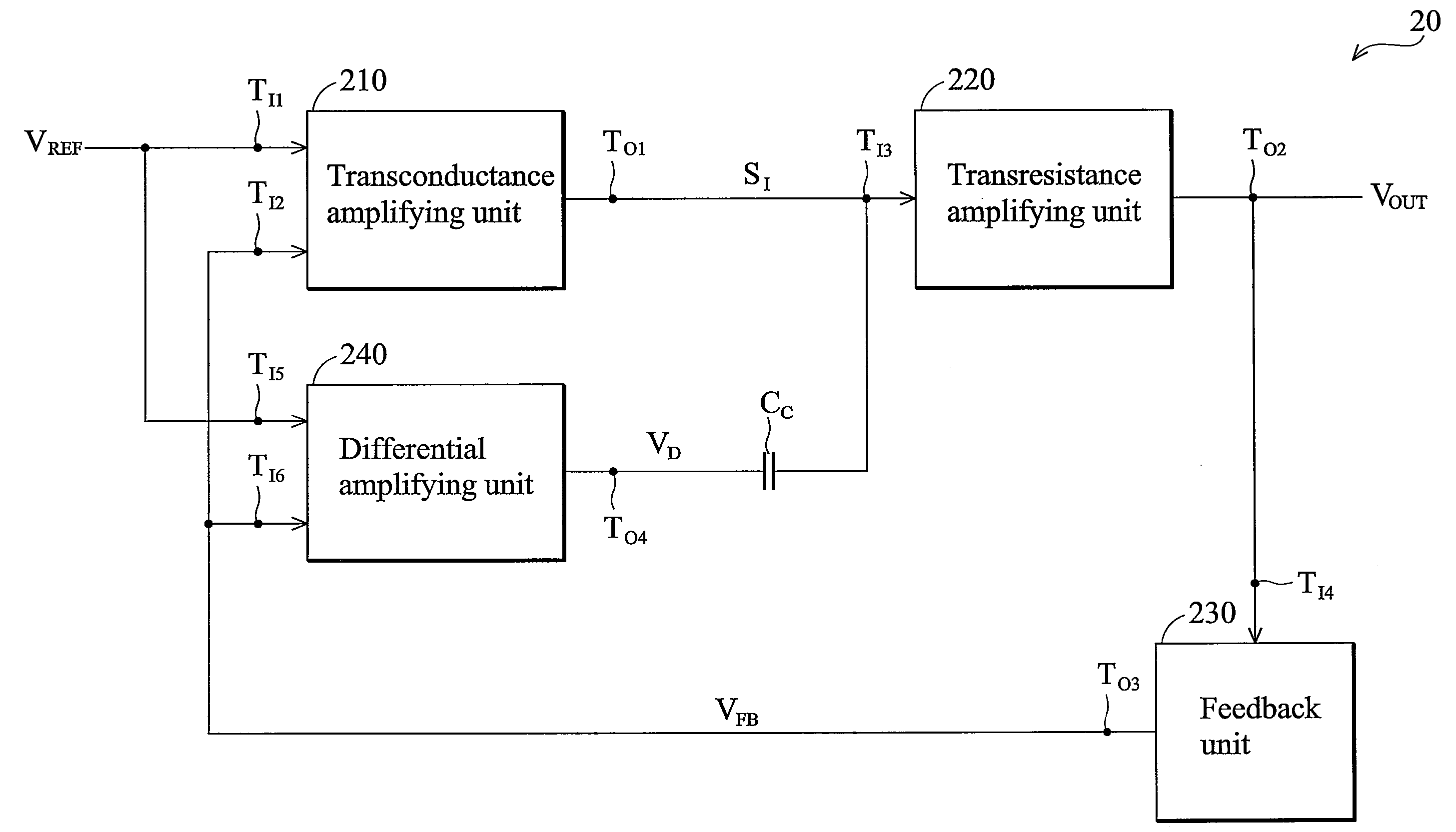
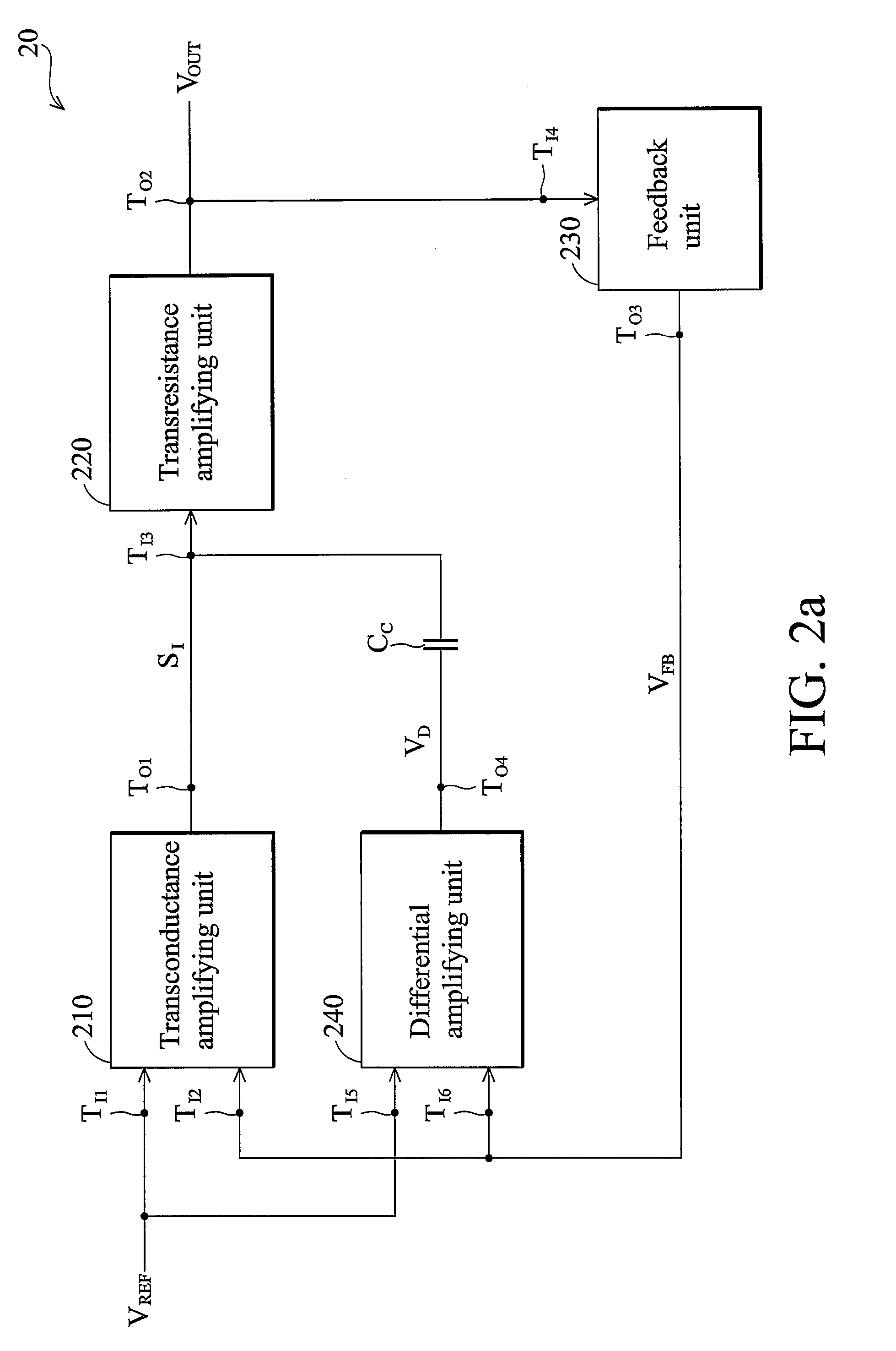
[0019]FIG. 2a is a schematic diagram of an exemplary embodiment of a voltage regulator. The voltage regulator 20 comprises a transconductance amplifying unit 210, a transresistance amplifying unit 220, a feedback unit 230, a differential amplifying unit 240, and a compensation capacitor Cc.

[0020]The transconductance amplifying unit 210 comprises inputs TI1, TI2 for receiving a reference voltage VREF and a feedback voltage VFB, respectively, and comprises an output TO1 for outputting current SI. The transresistance amplifying unit 220 comprises an input TI3 for receiving the current SI and transforms the current SI into an output voltage VOUT. Feedback unit 230 generate...


PUM


Abstract

A voltage regulator including a transconductance amplifying unit, a transresistance amplifying unit, a feedback unit, a differential amplifying unit, and a compensation capacitor. The transconductance amplifying unit includes two inputs for receiving a feedback voltage and a reference voltage, and includes an output for outputting a current. The transresistance amplifying unit includes an input for receiving the current, and transforming the current into an output voltage. The feedback unit generates the feedback voltage with reference to the output voltage. The differential amplifying unit includes two inputs for receiving the feedback voltage and the reference voltage, and includes an output for outputting a differential voltage. The compensation capacitor is coupled between the output of the differential amplifying unit and the input of the transresistance amplifying unit.

Description

BACKGROUND OF THE INVENTION[0001]1. Field of the Invention[0002]The invention relates to a voltage regulator, and more particularly to the compensation for a voltage regulator.[0003]2. Description of the Related Art[0004]The stability of performance of circuits having feedback is improved by providing compensation so as to increase phase margin. A well known technique for improving phase margin takes advantage of the Miller Effect, by adding a Miller-compensating capacitance in parallel with a gain stage, e.g., the output stage of a two stage amplifier circuit.[0005]A problem arises when the load capacitance seen by a circuit having compensating capacitance such as Miller-compensating capacitance becomes large. This requires the compensating capacitance to increase in value in order to maintain stability. Larger compensating capacitance, however, occupies more physical space. This is not a luxury that can be afforded in an environment where more circuits are integrated onto the same...

Claims


Application Information

Patent Timeline
IPC IPC(8): G05F1/575
CPCG05F1/575
Inventor LOU, CHIH-HONG
Owner MEDIATEK INC
Learn More