
Method of operating a fuel cell stack at low pressure and low power conditions

Inactive Publication Date: 2009-05-21
BALLARD POWER SYSTEMS
View PDF7 Cites 5 Cited by
  • Summary
  • Abstract
  • Description
  • Claims
  • Application Information

AI Technical Summary

Benefits of technology

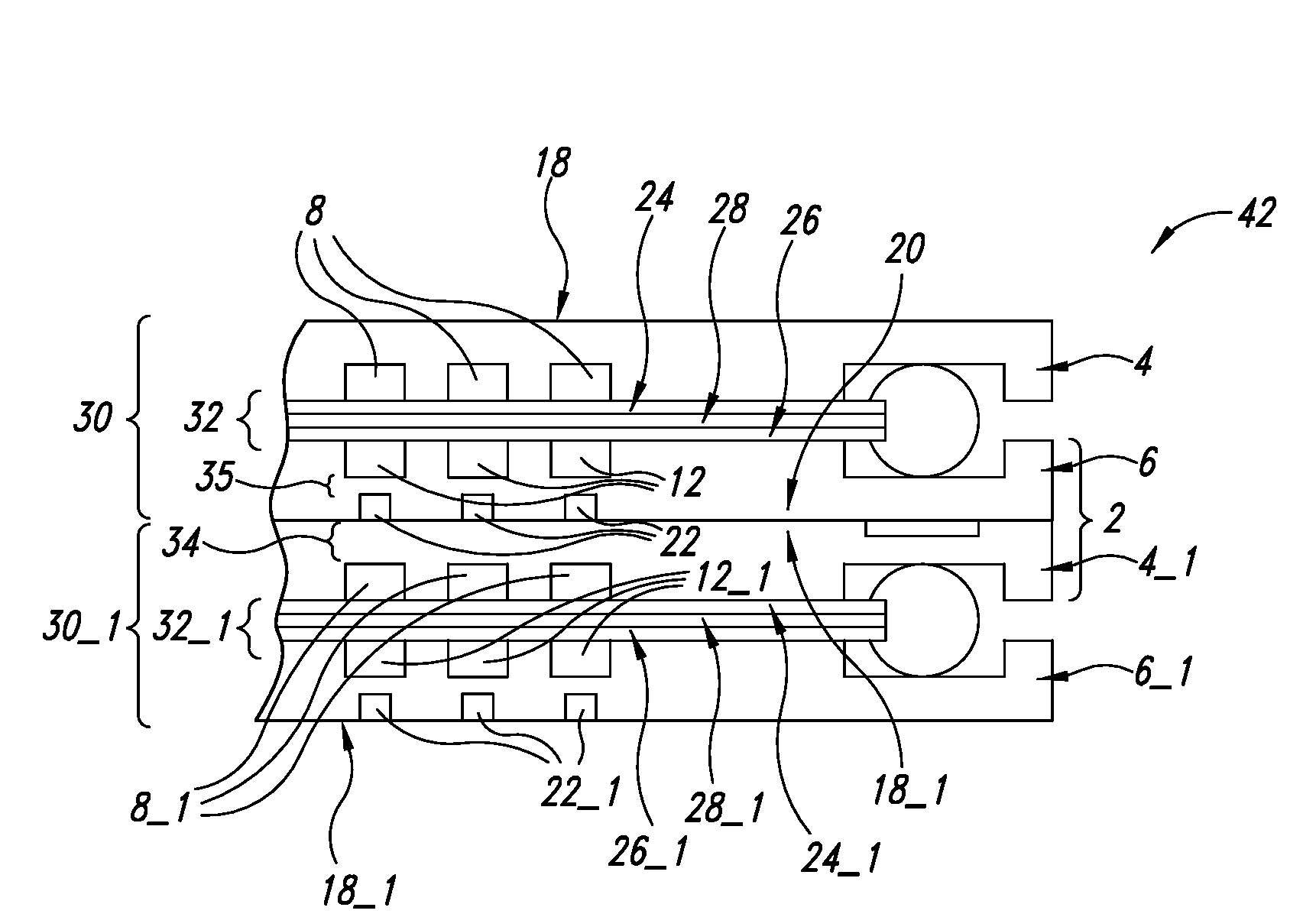
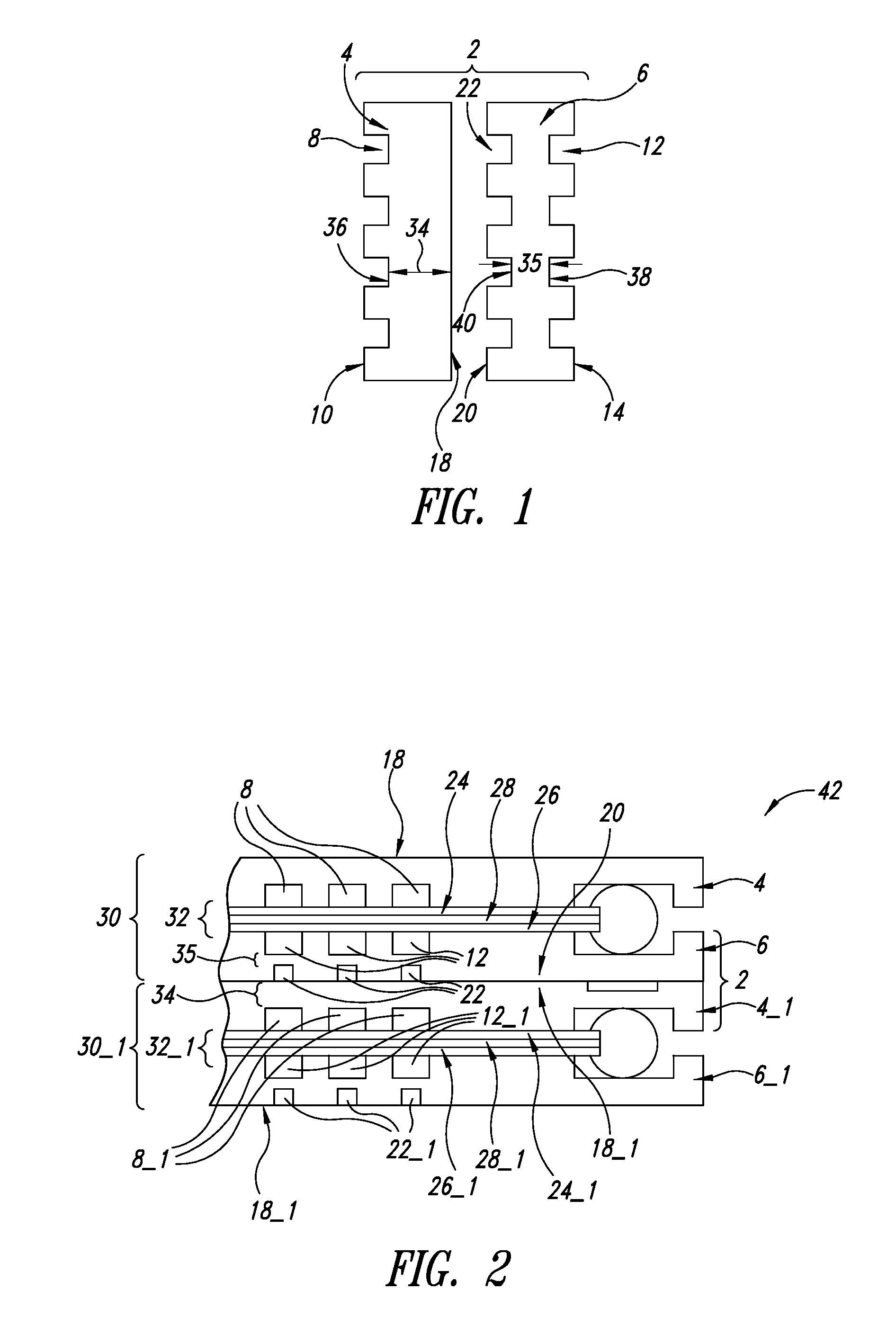
[0016]In brief, a method is provided for operating a low pressure drop fuel cell stack with improved performance stability at low pressure and low power operating conditions, wherein each fuel cell of the fuel cell stack comprises an anode flow field plate, a cathode flow field plate and a membrane electrode assembly, such that during low pressure and low power operation, the cathode flow field plate of each fuel cell has a higher heat transfer rate than the anode flow field plate of the same fuel cell.
[0018]To create a higher heat transfer rate in the cathode flow field plate than the heat transfer rate in the anode flow field plate, in one embodiment, the cathode flow field plate material has a higher thermal conductivity than the anode flow field plate material, for example, by using different materials for the anode and cathode flow field plates. Thus, during low pressure and power operation of the low pressure drop fuel cell stack, heat rejection from the reactant in the cathode flow fields of each fuel cell is higher than heat rejection from the reactant in the anode flow fields of the same fuel cell, thereby keeping the cathode of each fuel cell warmer than the anode of the same fuel cell.

Problems solved by technology

However, most commercially available blowers and fans pressurize the reactants to significantly lower pressures than conventional fuel cells, for example, up to 0.21 barg, thereby undesirably limiting the highest operating pressure.
An excess of water droplets is undesirable because the water droplets contribute to unstable performance (for example, water “flooding” in the anode and / or cathode), and may cause non-uniform reactant fluid flow and reactant starvation.
However, this results in an increase in the operating pressure to compensate for the pressure drop of the flow fields, thus increasing parasitic power consumption and decreasing fuel efficiency.
However, when operating low pressure fuel cells at low power, unstable fuel cell performance is often observed because a low amount of reactants are delivered to the fuel cells, thereby resulting in a reactant flow velocity that is inadequate to clear excessive liquid water in the flow fields of the low pressure fuel cell, particularly in the anode flow fields wherein the stoichiometry is typically minimized to maximize fuel efficiency.
However, all of these methods are also undesirable because they increase parasitic power consumption and decrease fuel efficiency.
However, power consumption is increased and fuel efficiency is decreased in order to run other system components to evaporate or remove excess liquid water.
Again, these methods consume extra parasitic power in order to prevent water from excessively flooding the cathode or to evaporate excess water, thereby preventing / recovering fuel cell performance loss due to cathode flooding.
During low power operation (for example, at a current density of less than 0.5 A / cm2), water produced at the cathode may migrate to the anode due to a water vapor pressure differential between the fuel stream and the oxidant stream in the anode and cathode flow fields, respectively, thus resulting in anode flooding.
Anode flooding is difficult to mitigate because fuel is usually supplied at a stoichiometry that is as low as possible in order to maximize fuel efficiency while sustaining the required power generation.
Furthermore, when running at low pressure (for example, in cases when blowers and / or fans are used to deliver the reactants to the fuel cell stack), the reactant flow velocity is insufficient to remove the condensed water vapor in the anode flow fields, thereby increasing performance instability.

Method used


Image

  • Method of operating a fuel cell stack at low pressure and low power conditions
  • Method of operating a fuel cell stack at low pressure and low power conditions
  • Method of operating a fuel cell stack at low pressure and low power conditions

Examples


example

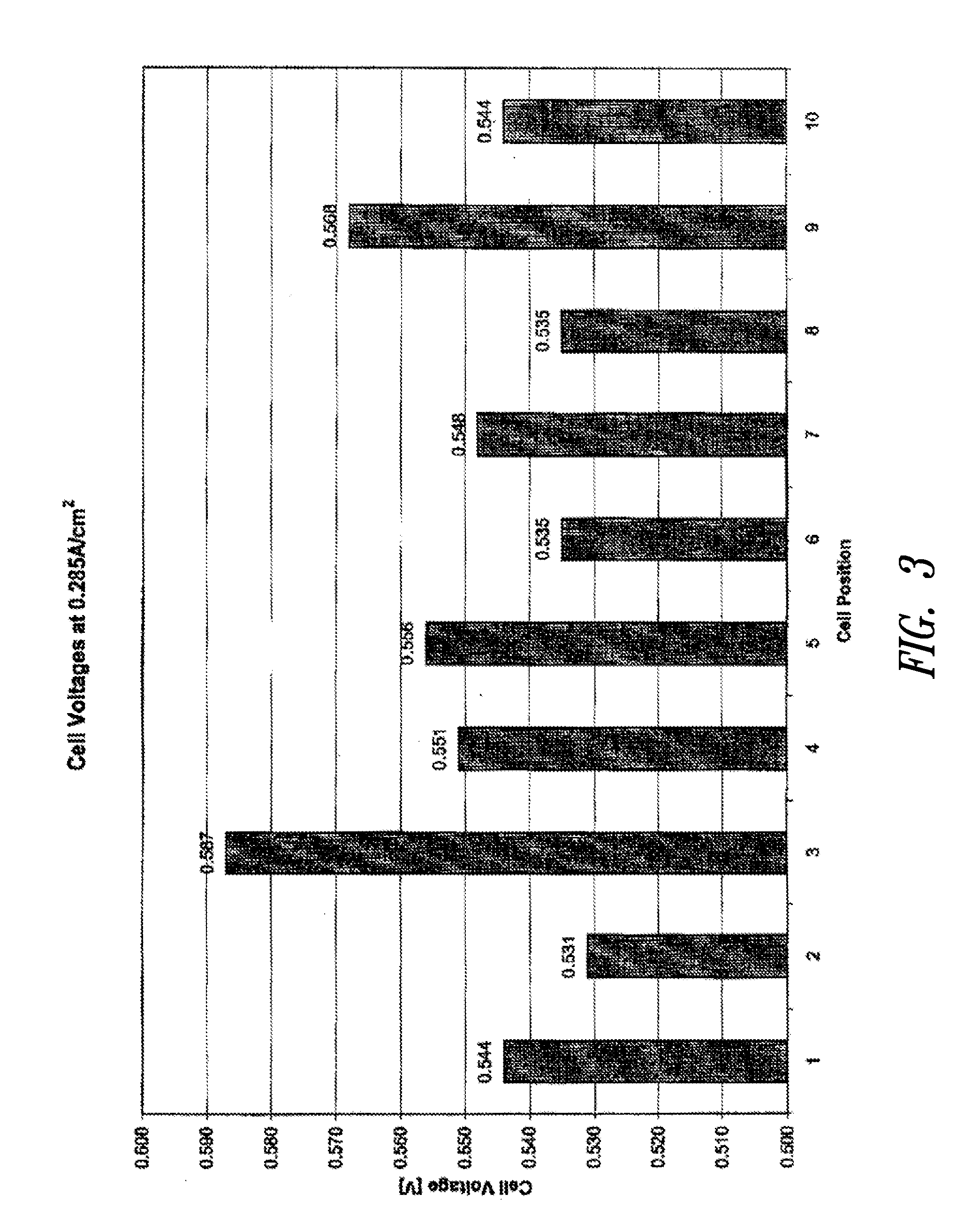
[0041]Two 10-cell fuel cell stacks were tested under the following conditions: diluted fuel (74% hydrogen, 20% carbon dioxide, 6% nitrogen) was supplied to the anode at a pressure of 17.2 kPag, a humidification temperature of 57° C. and a stoichiometry of 1.25, while air was supplied to the cathode at a pressure of 10.7 kPag, a humidification temperature of 57° C. and a stoichiometry of 2.0. The anode flow fields of both stacks had a pressure drop of 120 mbar while the cathode flow fields of both stacks had a pressure drop of 100 mbar. The anode flow field plate web thickness of the anode flow field plates in the first stack was 1.88-millimeters, while the anode flow field plate web thickness of the anode flow field plates in the second stack was 3.6-millimeters. Both stacks were operated at 0.285 A / cm2 for about 15 minutes.

[0042]FIG. 3 shows the average performance of each fuel cell in the first 10-cell stack comprising 1.88-millimeter web thickness anode flow field plates. The ave...


PUM


Abstract

A method of operating a low pressure drop fuel cell stack comprising a plurality of low pressure drop fuel cells wherein during low pressure and low power operation, a heat transfer rate of a cathode flow field plate of each fuel cell is greater than a heat transfer rate of an anode flow field plate of the same fuel cell. Thus, a temperature gradient is created between an anode electrode and a cathode electrode of each fuel cell, as well as reactant fluids in at least one anode flow field and at least one cathode flow field of the same fuel cell.

Description

CROSS-REFERENCE TO RELATED APPLICATION[0001]This application is a continuation of PCT Application No. PCT / US2005 / 041863, filed Nov. 18, 2005, now pending, which application is incorporated herein by reference in its entirety.BACKGROUND[0002]1. Technical Field[0003]The present invention relates to a method of operating fuel cell stacks, in particular, operating solid polymer fuel cell stacks under low pressure and low power operating conditions.[0004]2. Description of the Related Art[0005]Electrochemical fuel cells convert fuel and oxidant into electricity. Solid polymer electrochemical fuel cells generally employ a membrane electrode assembly that includes an ion exchange membrane or solid polymer electrolyte disposed between two electrodes typically comprising a layer of porous, electrically conductive sheet material, such as carbon fiber paper or carbon cloth. The membrane electrode assembly comprises a layer of catalyst, typically in the form of finely comminuted platinum, at eac...

Claims


Application Information

Patent Timeline
IPC IPC(8): H01M8/00H01M8/02
CPCH01M8/04089H01M8/04731H01M8/04753Y02E60/50H01M8/242H01M2008/1095H01M8/0491H01M8/0258H01M8/0267H01M8/2404
Inventor WOZNICZKA, BOGUSLAW M.WONG, ALFRED N.F.COLBOW, KEVIN M.
Owner BALLARD POWER SYSTEMS
Learn More