Patch antenna

a patch antenna and patch antenna technology, applied in the direction of resonant antennas, substantially flat resonant elements, radiating element structural forms, etc., can solve the problems of low transmit power of mobile devices, limited sector coverage of dual-polarized patch antenna arrays, and limited operating range of access points, etc., to achieve wide horizontal beamwidth and large sector coverage

Active Publication Date: 2009-08-13
HMD GLOBAL
View PDF4 Cites 13 Cited by
  • Summary
  • Abstract
  • Description
  • Claims
  • Application Information

AI Technical Summary

Benefits of technology

[0012]The approach presented allows the design of high-performance dual- or circularly-polarized antenna arrays with wide horizontal beamwidths and large sector coverage.

Problems solved by technology

The operating range is typically limited by a low transmit power of the mobile device such as, e.g., a phone, a PDA, a laptop or the like.
The sector coverage of dual-polarized patch antenna arrays is typically limited to below 100 degrees.
An operating range of an access point is typically limited by the transmit power provided by the mobile terminal.
This results in a very narrow beam in the vertical direction.

Method used


Image

  • Patch antenna
  • Patch antenna
  • Patch antenna

Examples


Embodiment Construction

[0043]Reference will now be made in detail to the preferred embodiments of the present invention, examples of which are illustrated in the accompanying drawings, wherein like reference numerals refer to like elements throughout.

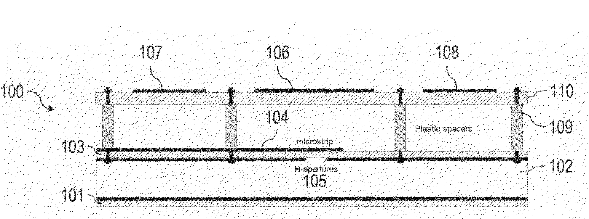
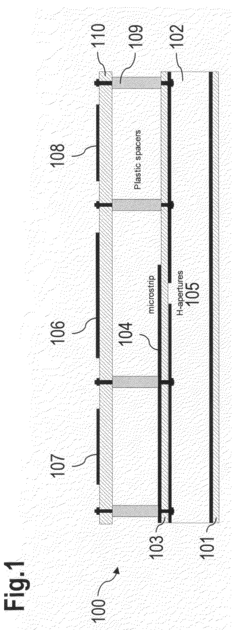
[0044]The approach described herein in particular enables an application of parasitic patches to a dual-polarized microstrip patch antenna using corner-feeding and thus diagonal radiating modes.

[0045]Hence, preferably only two parasitic patches are needed for shaping the beamwidths of both polarizations at the same time.

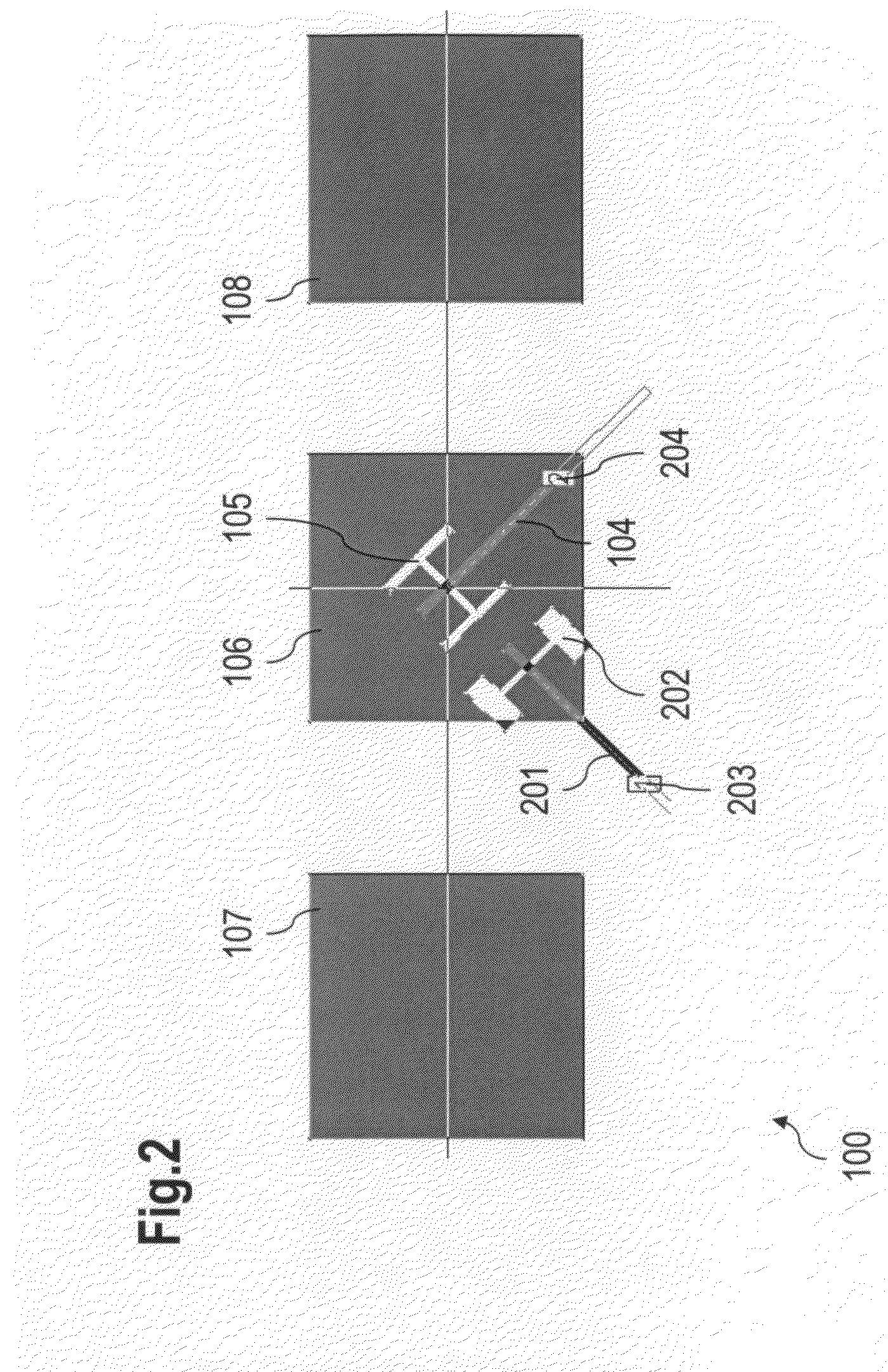
[0046]Parasitic patches can advantageously be excited by the diagonal radiating modes, although coupling may be not as direct compared to traditional E- and H-plane coupling. Therefore, the parasitic patches can be quite close to the main radiator, and may be, e.g., almost the same size as said main radiator.

[0047]A resulting beamwidth and a main beam ripple may be controlled or adjusted by, e.g., reducing or increasing a parasitic patch size ...


PUM


Abstract

A patch antenna has a primary radiator, a dual microstrip feed line configured to utilize corner-feeding to enable substantially diagonal radiating modes, and at least two parasitic patches that are arranged adjacent and on opposite sides to the primary radiator.

Description

CROSS REFERENCE TO RELATED APPLICATIONS[0001]This application is based on and hereby claims priority to European Application No. EP08000696 filed on Jan. 15, 2008, the contents of which are hereby incorporated by reference.BACKGROUND OF THE INVENTION[0002]J. Säily, “Proximity-coupled and dual-polarized microstrip patch antenna for WCDMA base station arrays”, Proceedings of the 2006 Asia-Pacific Microwave Symposium, Dec. 12-15, 2006, Yokohama, Japan, shows a dual-polarized microstrip patch antenna. The antenna uses proximity-coupled microstrip feed lines along the patch corners and covers Wideband Code Division Multiple Access / Universal Mobile Telecommunications System (WCDMA / UMTS) band with only a single radiating patch. The corner-fed patch arrangement results in two orthogonal linear polarizations along the patch diagonals with high isolation. The presented antenna can be applied in dual-slant polarized base station antenna arrays.[0003]A Wireless Local Area Network (WLAN) access ...

Claims


Application Information

Patent Timeline
Patent Type & Authority Applications(United States)
IPC IPC(8): H01Q9/04H01Q1/24
CPCH01Q1/243H01Q19/005H01Q9/0407H01Q1/246
Inventor SAILY, JUSSI
Owner HMD GLOBAL
Why Eureka
Try Eureka