Liquid crystal display apparatus

a technology of liquid crystal display and display image, which is applied in the direction of static indicating devices, non-linear optics, instruments, etc., can solve the problems of perceived luminance unevenness on display image, and achieve the effect of suppressing luminance unevenness and preventing the weakened contrast improvement

Active Publication Date: 2009-08-13
HISENSE VISUAL TECH CO LTD
View PDF2 Cites 17 Cited by
  • Summary
  • Abstract
  • Description
  • Claims
  • Application Information

AI Technical Summary

Benefits of technology

[0008]The present invention has been made in view of these circumstances, and an object thereof is to provide a liquid crystal display apparat

Problems solved by technology

In some cases, problems that luminance unevenness is perceived on the

Method used


Image

  • Liquid crystal display apparatus
  • Liquid crystal display apparatus
  • Liquid crystal display apparatus

Examples


first embodiment

[0038]A liquid crystal display apparatus according to a first embodiment of the present invention will now be described with reference to FIGS. 1 to 19(f).

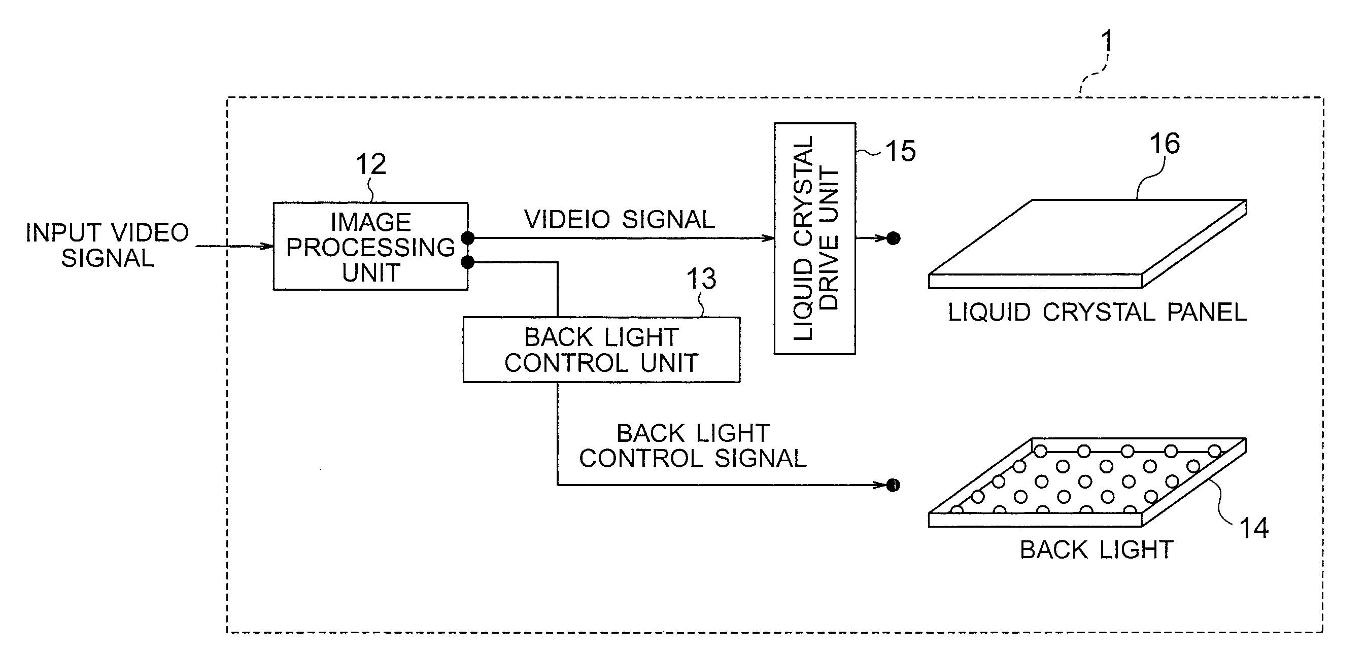
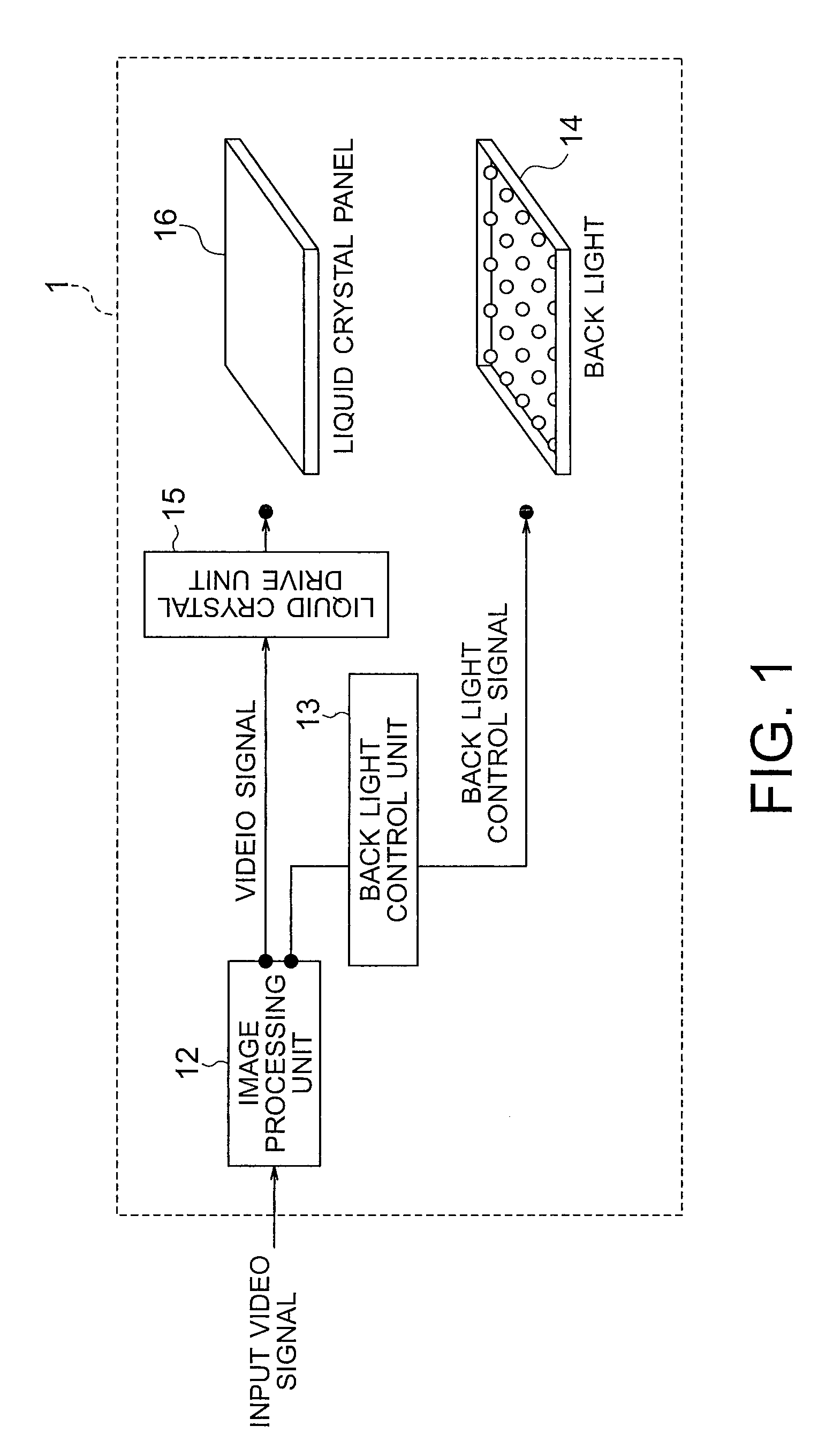
[0039]The liquid crystal display apparatus according to the present embodiment is shown in FIG. 1. A liquid crystal display apparatus 1 according to the present embodiment includes an image processing unit 12, a back light control unit 13, a back light 14, a liquid crystal drive unit 15, and a liquid crystal panel 16. A video signal is input from the outside to the image processing unit 12. The image processing unit 12 determines luminance of the back light 14 and corrects the video signal on the basis of the input video signal, and outputs resultant signals. The back light control unit 13 outputs a back light control signal to control the back light 14 on the basis of the luminance of the back light 14 determined by the image processing unit 12. The back light 14 is supplied with the back light control signal from the back light ...

second embodiment

[0097]A liquid crystal display apparatus according to a second embodiment of the present invention will now be described.

[0098]The liquid crystal display apparatus according to the second embodiment is the same in basic configuration as that according to the first embodiment. However, the liquid crystal display apparatus according to the second embodiment has a feature that amplitude of spatial frequency components in light emission luminance distribution of a single light source is equal to or greater than a second threshold over a spatial frequency range from the spatial frequency of the direct current component to a first spatial frequency.

[0099]Light Emission Luminance Distribution of Light Source

[0100]An example of light emission luminance distribution of a certain single light source in the liquid crystal display apparatus according to the present embodiment is shown in FIGS. 20A and 20B. FIG. 20A is a diagram showing light emission luminance distribution of a light source acc...

third embodiment

[0119]A liquid crystal display apparatus according to a third embodiment of the present invention will now be described.

[0120]The liquid crystal display apparatus according to the present embodiment is the same in basic configuration as that according to the first embodiment. However, the liquid crystal display apparatus according to the present embodiment has a feature that amplitude of spatial frequency components in light emission luminance distribution of a single light source is equal to or less than a first threshold at spatial frequencies of at least 1 / (distance between light sources) and is equal to or greater than a second threshold over a spatial frequency range from the spatial frequency of the direct current component to a first spatial frequency. In other words, the liquid crystal display apparatus according to the present embodiment has a feature obtained by combining the feature of the liquid crystal display apparatus according to the first embodiment and the feature ...


PUM


Abstract

A liquid crystal display apparatus includes: a liquid crystal panel having a plurality of pixels arranged in a matrix form; a back light having a plurality of light sources controlled individually in light emission luminance to supply light to the liquid crystal panel; an image processing unit configured to calculate luminance setting values respectively of the light sources of the back light and correct the video signal; a back light control unit configured to control the back light on the basis of luminance setting values; and a liquid crystal drive unit configured to drive the liquid crystal panel on the basis of the corrected video signal. In strength distribution of light incident, a relative strength compared with a direct component in spatial frequency domain is equal to or less than a first threshold in a spatial frequency region having a value of at least 1.

Description

CROSS-REFERENCE TO RELATED APPLICATION[0001]This application is based upon and claims the benefit of priority from prior Japanese Patent Application No. 2007-318837 filed on Dec. 10, 2007 in Japan, the entire contents of which are incorporated herein by reference.BACKGROUND OF THE INVENTION[0002]1. Field of the Invention[0003]The present invention relates to a liquid crystal display apparatus.[0004]2. Related Art[0005]Conventionally, back light luminance control using a plurality of light sources capable of exercising light emission control individually is conducted in liquid crystal display apparatuses with the object of attaining a high contrast and lower power dissipation.[0006]For example, in JP-A 2007-34251 (KOKAI), the back light is formed of a plurality of light sources and light emission luminance is controlled for each light source.[0007]In the conventional liquid crystal display apparatuses, however, spatial distribution of strength of light incident on the liquid crystal ...

Claims


Application Information

Patent Timeline
IPC IPC(8): G09G3/36
CPCG02F1/133621G02F2001/133601G09G3/3426G09G2360/16G09G2320/0238G09G2320/0646G09G2330/021G09G2320/0233G02F1/133601
Inventor NONAKA, RYOSUKEBABA, MASAHIROITOH, GOH
Owner HISENSE VISUAL TECH CO LTD
Why Eureka
Try Eureka