

Circuit breaker
a circuit breaker and circuit technology, applied in the field of circuit breaker, can solve the problems of increasing the size of the device and increasing the size of the device and the power loss of the transmission network, and increasing the cost. , to achieve the effect of improving the current-limiting performance, reducing the size of the device and cos
- Summary
- Abstract
- Description
- Claims
- Application Information
AI Technical Summary
Benefits of technology
Problems solved by technology
Method used
Image

Examples
first exemplary embodiment
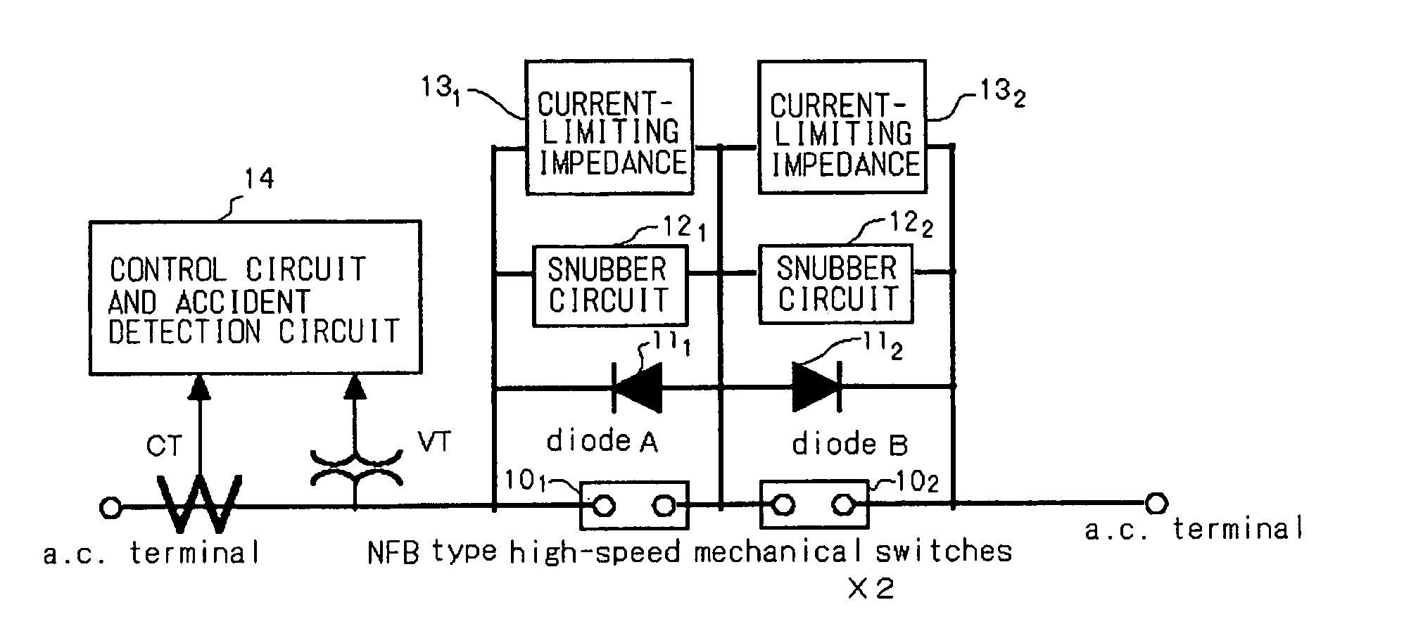
[0084]FIG. 1 shows the configuration of an exemplary embodiment of the present invention. Referring to FIG. 1, the present exemplary embodiment is directed to a hybrid type semiconductor current-limiting circuit breaker that makes use of both semiconductor devices and mechanical switches. The high-speed mechanical switches 101 and 102 are connected in series with each other. A diode 111, a snubber circuit 121 and a current-limiting impedance 131 are connected in parallel with the high-speed mechanical switch 101, whilst a diode 112, a snubber circuit 122 and a current-limiting impedance 132 are connected in parallel with the high-speed mechanical switch 102. The diode 111 has its anode connected to the anode of the diode 112. An anode connection point of the diodes is connected to a connection point of the high-speed mechanical switches. In the present embodiment, the high-speed mechanical switches 101 and 102 are formed by NFB high-speed mechanical switches, though not in the meani...
second embodiment
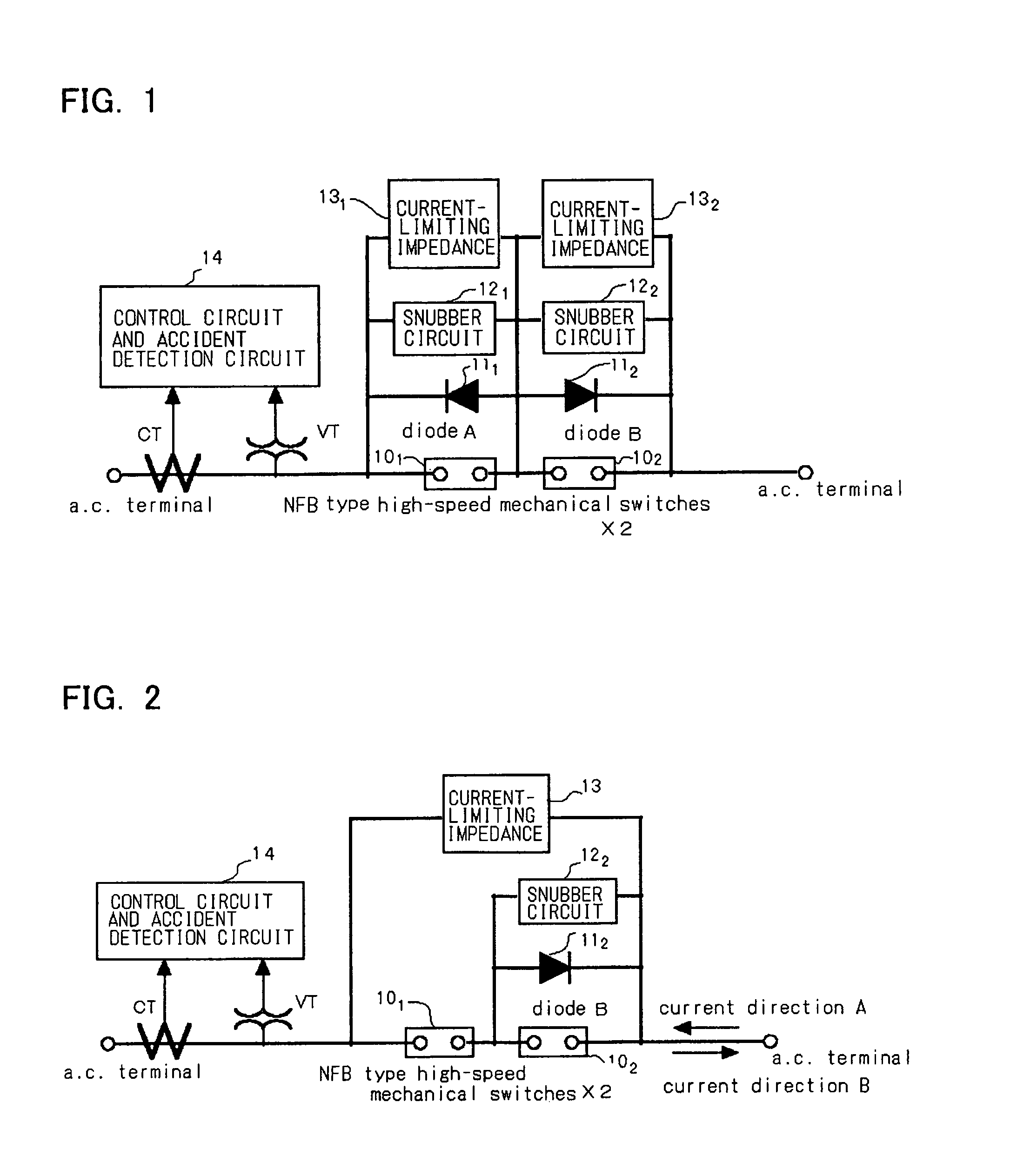
[0101]FIG. 2 is a diagram showing the configuration of a second exemplary embodiment of the present invention. Referring to FIG. 2, only the diode B (112) is provided for the high-speed mechanical switch 102. In the present exemplary embodiment, the high-speed mechanical switches 101 and 102 are made up by NFB type high-speed mechanical switches, though not in the sense of restricting the present invention.
[0102]The operation of the second exemplary embodiment is now described. During the normal operation, current flows through the high-speed mechanical switches 101 and 102, while no current or only the leakage current flows through the diode B (112), in a manner similar to the first exemplary embodiment shown in FIG. 1.
[0103]On detection of the fault current, the two high-speed mechanical switches 101 and 102 are opened, and hence arc plasma is generated across the electrodes of the high-speed mechanical switches. If the current direction at this time point is as indicated by arrow...
third exemplary embodiment
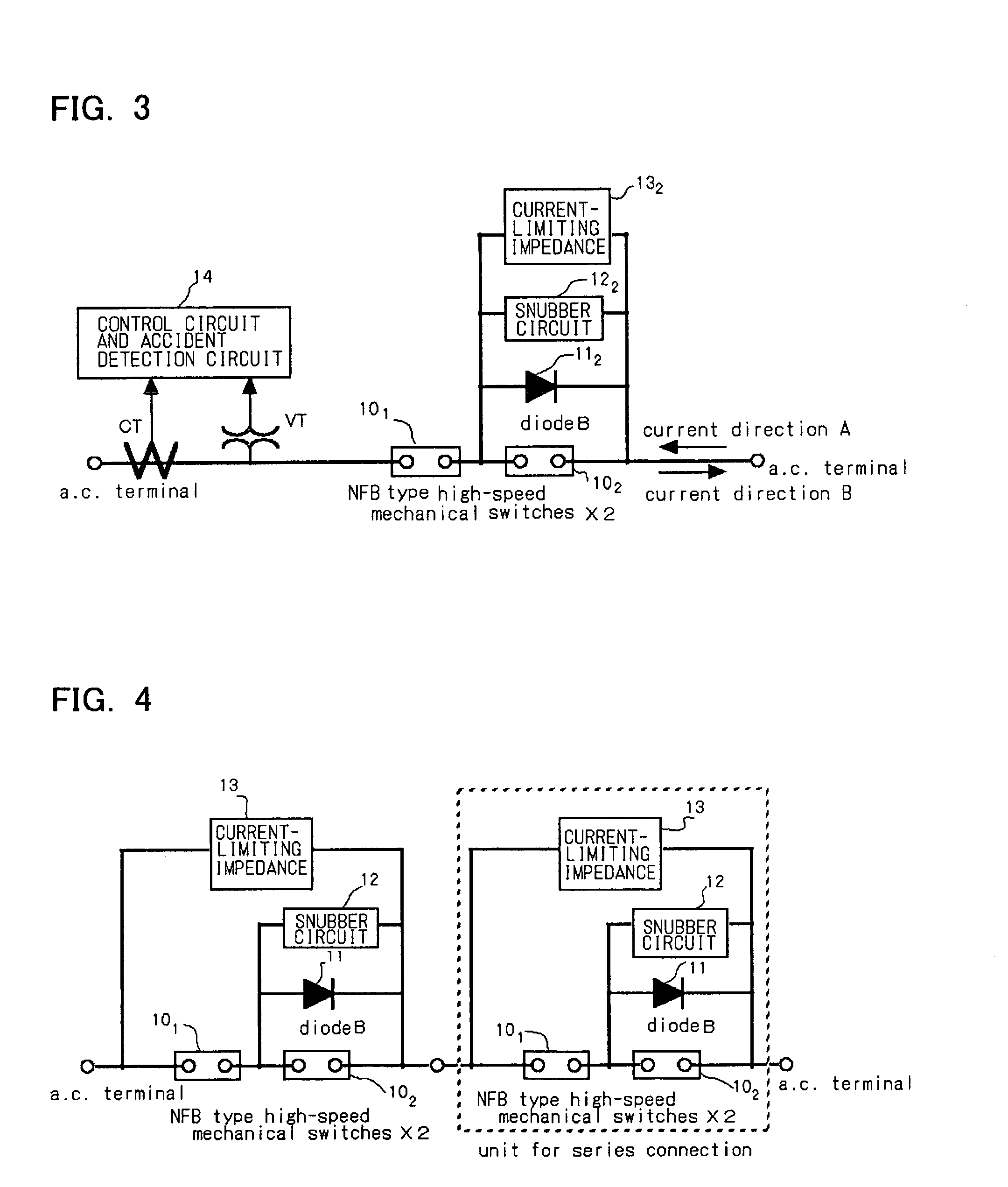
[0106]In the exemplary embodiment of FIG. 2, the high-speed mechanical switches 101 and 102 are connected in series with each other, while no diode is connected to the high-speed mechanical switches 101. Hence, the circuit shown is able to interrupt the current completely. This is shown as a third exemplary embodiment in FIG. 3.
[0107]In a configuration shown in FIG. 3, the operation during the normal operation is the same as that of FIGS. 1 and 2. On detection of the fault current, the high-speed mechanical switches 101, 102 are opened, and arc plasma is generated across each of the electrodes. If the current flowing direction is as indicated by arrow B, the current commences to be transferred to the diode B (112). If the current flowing direction is the reverse direction, the arc plasma across each of the electrodes of the high-speed mechanical switches is extinguished after one half cycle, and the current flows through the current-limiting impedance 132, so that the current-limiti...
PUM
 Abstract
Description
Claims
Application Information