Wall racer toy vehicles

a toy vehicle and wall race technology, applied in the direction of toys, remote control toys, vehicle components, etc., can solve problems such as difficulty in providing workable vehicles

Active Publication Date: 2009-08-13
CLARK JR LEONARD R +1
View PDF27 Cites 17 Cited by
  • Summary
  • Abstract
  • Description
  • Claims
  • Application Information

AI Technical Summary

Benefits of technology

[0006]More specifically, one or more battery-powered fans draw air from around all or defined portions of the periphery of the chassis of the Wall Racer through a carefully-shaped duct formed between the undersurface of the chassis and a juxtaposed surface, so that the air in the portion of the duct immediately adjacent the surface flows at high velocity. According to Bernouilli's Principle, this high-velocity air stream is of low pressure; the differential between this low-pressure air stream and the relatively greater pressure of the surrounding air urges the vehicle against the surface, allowing it to adhere to vertical surfaces, such as walls...

Problems solved by technology

Because the air stream must be freely flowing to attain high velocity, seals such as required for wall-climbing ...

Method used


Image

  • Wall racer toy vehicles
  • Wall racer toy vehicles
  • Wall racer toy vehicles

Examples


first embodiment

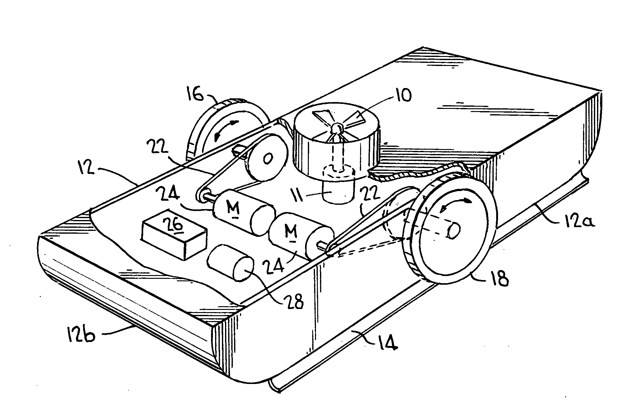
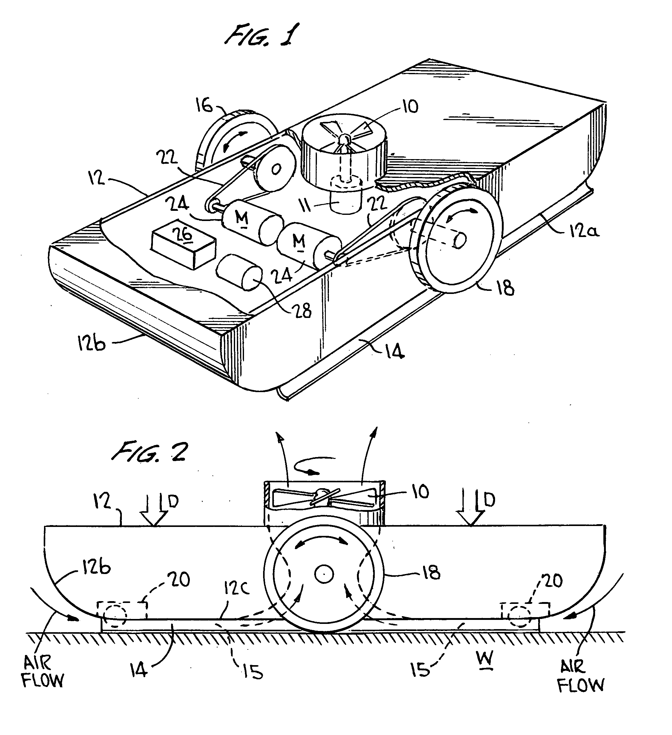
[0020]For example, FIGS. 1 and 2 show respectively a perspective and an elevation in partial cross-section of the Wall Racer, which as noted is generally elongated and could readily be fitted with a model race car or other vehicle body (not shown). As mentioned above, in order that downforce urging the Wall Racer against an abutting surface W (hereinafter simply “the wall”) can be developed, a high velocity stream of air is induced to flow in an underbody venturi duct formed between the undersurface of the chassis of the Wall Racer and the wall W. According to Bernouilli's Principle, as above, such a high velocity stream of air will be of reduced pressure with respect to the ambient air. The differential between this reduced pressure and the surrounding atmospheric pressure generates a resultant force D, termed “downforce” where, as here, its direction is such as to urge the vehicle “downwardly” toward the wall W. The amount of downforce D developed is proportional to the area over ...

third embodiment

[0024]By comparison, in the generally circular third embodiment of the Wall Racer shown in FIGS. 8 and 9 (discussed further below) a substantial distance exists between all points on the outer periphery of the undersurface of its chassis and the centrally-located exhaust duct, so that the airflow in this embodiment is radially inwardly from all directions, the downforce is developed uniformly around the chassis, and no skirts need to be fitted.

[0025]As noted, the differential in pressure and thus the downforce developed is a function of the air velocity, which up to a point can be increased by reducing the cross-sectional area of the duct formed between the underside of the chassis and the wall W, that is, by reducing the ground clearance of the Wall Racer. However, if the cross-sectional area is reduced too much, turbulence will impede flow and reduce the desired effect; reducing the ground clearance would also increase the Wall Racer's sensitivity to surface irregularities and the...

second embodiment

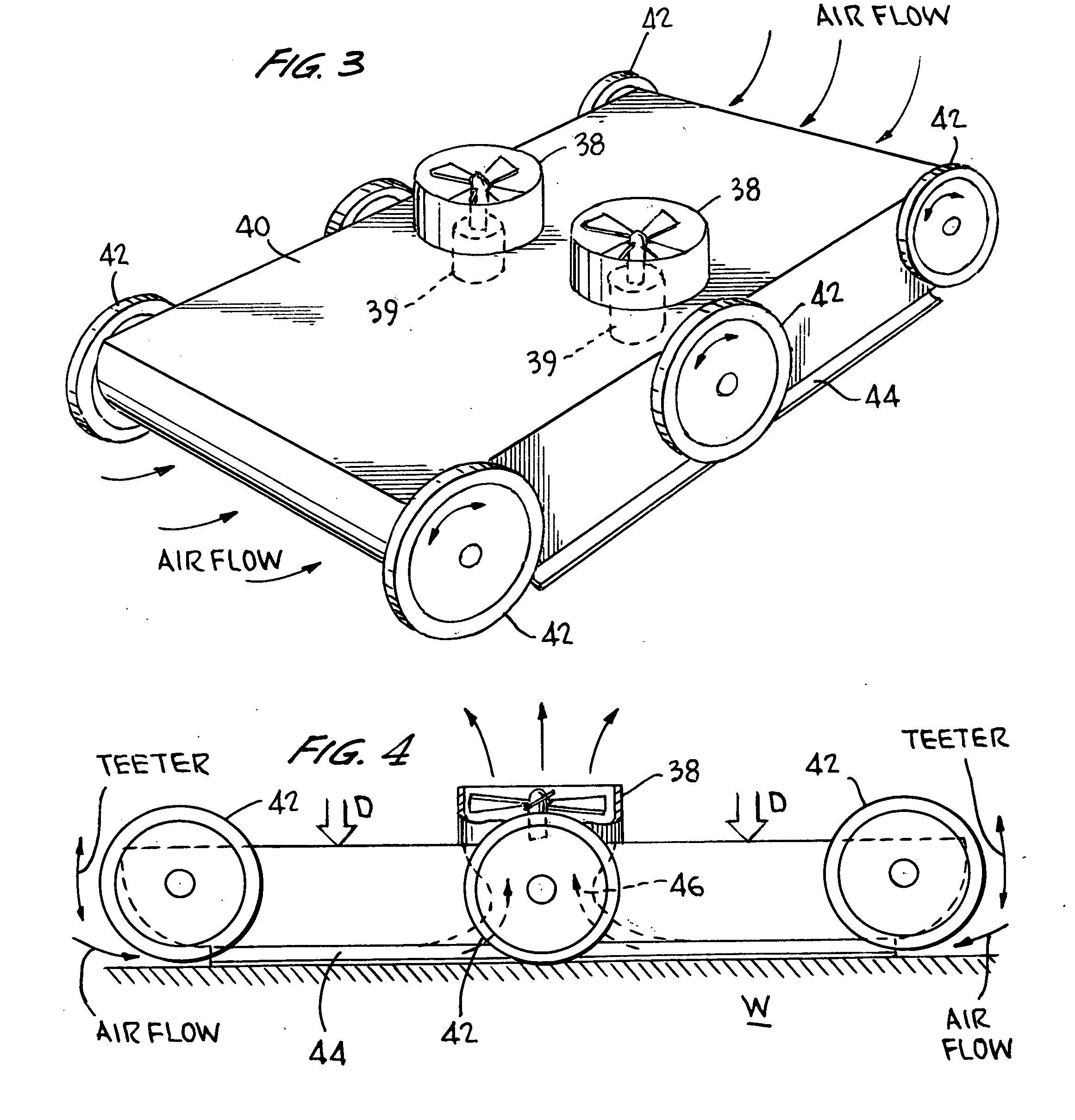
[0029]FIGS. 3 and 4 show the Wall Racer; this embodiment appears likely to correspond to the earliest production version of the Wall Racer. FIG. 12 provides detailed dimensional information concerning this embodiment, and preproduction specifications are provided below as well.

[0030]As shown by FIG. 3, in this embodiment two exhaust fans 38 are provided, spaced laterally from another on the transverse centerline of the chassis 40, and each fan being driven by a motor 39 with the fan mounted directly on the motor shaft. Six drive wheels 42 are provided, three on either side of the chassis 40, with the three wheels 42 on either side of the chassis being geared (or belt-driven) to one another so as to be driven in common by two separately radio-controlled motors. The radio control receiver and battery are not shown, as being generally within the skill of the art. FIGS. 5, 6, and 7 (discussed below) show a preferred gear train and motor arrangement. Thus, as in the FIG. 1 embodiment, st...


PUM


Abstract

A motorized toy vehicle or Wall Racer that is capable of operating on vertical and inverted horizontal surfaces such as walls and ceilings, while being manufacturable at reasonable cost and operable on batteries having sufficient lifetime as to be enjoyable. One or more battery-powered fans draw air from around all or defined portions of the periphery of the chassis of the Wall Racer through a carefully-shaped duct, so that the air in the portion of the duct immediately adjacent the surface flows at high velocity and low pressure; the relatively greater pressure of the surrounding air urges the vehicle against the surface, allowing it to operate on vertical surfaces, such as walls, or inverted on horizontal surfaces, such as ceilings.

Description

CROSS-REFERENCE TO RELATED APPLICATION[0001]This application is a continuation-in-part of Ser. No. 11 / 177,428, filed Jul. 11, 2005, which claimed priority from U.S. provisional application 60 / 640,041, filed Dec. 30, 2004. This application also claims priority from United States design patent application Ser. No. 29 / 312,447, filed Oct. 21, 2008.FIELD OF THE INVENTION[0002]This invention relates to radio-controlled motorized toy vehicles capable of operation on surfaces of all orientations, e.g., walls and ceilings as well as floors.BACKGROUND OF THE INVENTION[0003]Radio-controlled motorized toy vehicles, that is, vehicles driven by motors and steered responsive to commands transmitted remotely, are of course well-known. Toy vehicles that are very sophisticated in terms of their suspension and steering systems are available and are very popular. A toy vehicle that operated other than on essentially horizontal surfaces, e.g., which could operate on a vertical wall, or inverted on a cei...

Claims


Application Information

Patent Timeline
IPC IPC(8): A63H30/00
CPCA63H17/26B62D57/024B62D37/02A63H30/04A63H17/262
Inventor CLARK, JR., LEONARD R.GREENE, JR., H. PETER
Owner CLARK JR LEONARD R
Why Eureka
Try Eureka