Systems and Methods for Exhaust Gas Recirculation (EGR) for Turbine Engines

a technology of turbine engines and exhaust gas recirculation, which is applied in the direction of machines/engines, mechanical equipment, and non-fuel substance addition to fuel, etc., can solve the problems of undesirable variations in efficiency, output, output, stress, etc., and achieve the effect of reducing operational variation and/or impa

Inactive Publication Date: 2009-08-20
GENERAL ELECTRIC CO
View PDF20 Cites 91 Cited by
  • Summary
  • Abstract
  • Description
  • Claims
  • Application Information

AI Technical Summary

Benefits of technology

[0005]A technical effect of an embodiment of the invention may be the reduction...

Problems solved by technology

If the ambient temperature at the inlet of a turbine engine deviates from that optimal temperature range, then the gas...

Method used


Image

  • Systems and Methods for Exhaust Gas Recirculation (EGR) for Turbine Engines
  • Systems and Methods for Exhaust Gas Recirculation (EGR) for Turbine Engines
  • Systems and Methods for Exhaust Gas Recirculation (EGR) for Turbine Engines

Examples


Embodiment Construction

[0015]Embodiments of the invention now will be described more fully hereinafter with reference to the accompanying drawings, in which some embodiments of the invention are shown. This invention may, however, be embodied in many different forms and should not be construed as limited to the embodiments set forth herein; rather, these embodiments are provided so that this disclosure will be thorough and complete, and will fully convey the scope of the invention to those of ordinary skill in the art. Like numbers refer to like elements throughout.

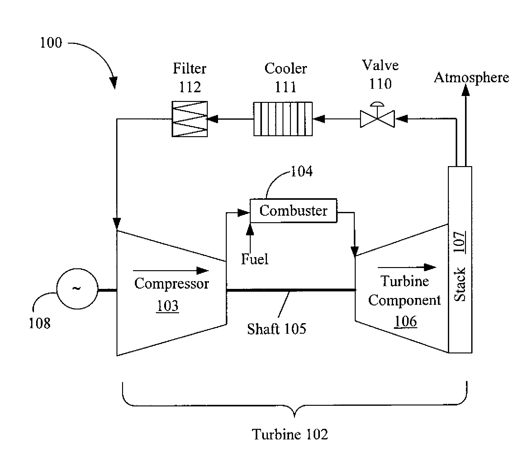
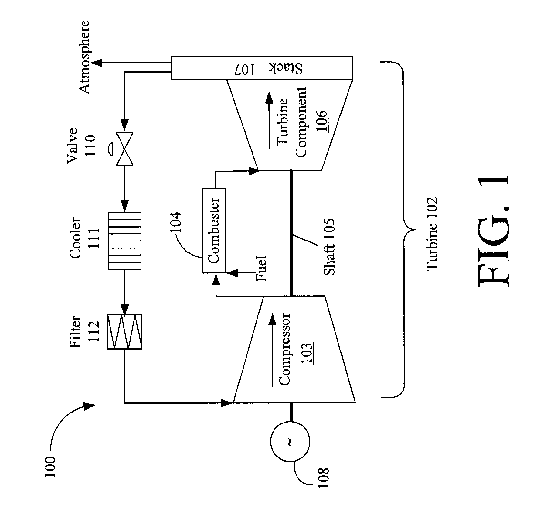
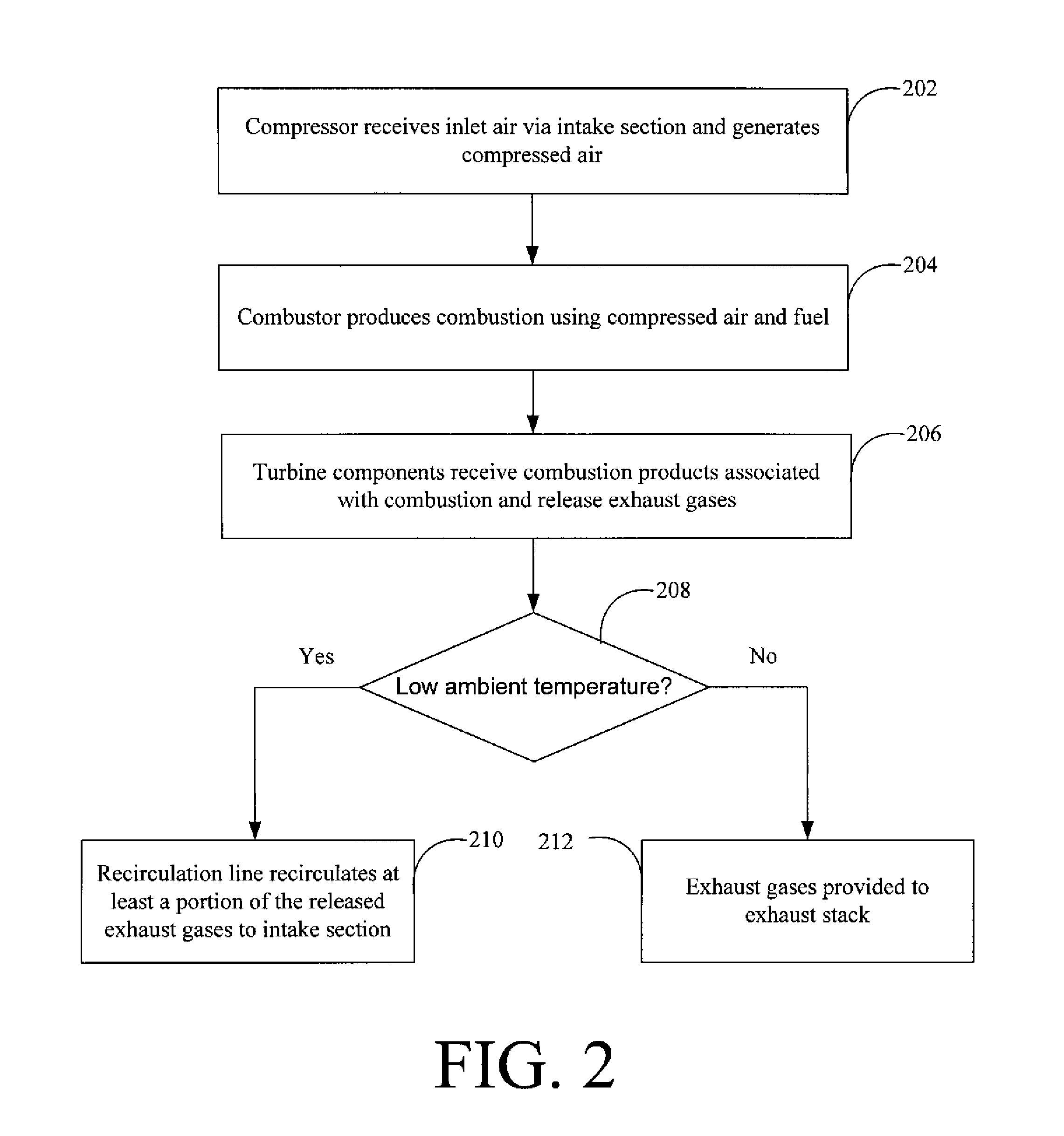
[0016]In general, embodiments of the invention may provide systems and methods for recirculating exhaust gases to an intake (e.g., inlet) of the turbine engine. By recirculating the exhaust gases, the ambient temperature of the inlet air of the turbine engine may be raised appropriately, according to an example embodiment of the invention. Indeed, the recirculation of exhaust gases may allow for reducing the operational variation and impact on ...


PUM


Abstract

Systems and methods may be provided for exhaust gas recirculation. The systems and methods may include receiving, via an intake section, inlet air at an input of a compressor, generating compressed air at the compressor using the received inlet air, and providing the compressed air from the compressor to a combustor, where the combustor produces combustion involving the compressed air and fuel. The systems and methods may also include receiving combustion products associated with the combustion at a turbine component, where the turbine component releases exhaust gases, and recirculating at least a portion of the exhaust gases to the intake section via a recirculation line, where the recirculated exhaust gases raise a temperature of the inlet air.

Description

BACKGROUND OF THE INVENTION[0001]1. Field of the Invention[0002]Aspects of embodiments of the invention relate generally to turbine engines, and more particularly, to the use of exhaust gas recirculation (EGR) for turbine engines.[0003]2. Background of the Invention[0004]Gas turbine engines are typically tuned to an optimal temperature range. If the ambient temperature at the inlet of a turbine engine deviates from that optimal temperature range, then the gas turbine engine and / or combined cycle may experience undesirable variations in efficiency, performance, output, stress, etc. Accordingly, there is a need in the industry for maintaining the ambient temperature of the inlet of the turbine engine at an optimal temperature under certain conditions in order to reduce operational variations.SUMMARY OF THE INVENTION[0005]A technical effect of an embodiment of the invention may be the reduction of operational variation and / or impact on turbine engines and / or the combined cycle.[0006]Ac...

Claims


Application Information

Patent Timeline
IPC IPC(8): F02B33/44
CPCF02C1/08Y02E20/16F02C6/18
Inventor ALJABARI, SAMERBOWMAN, MICHAEL JOHNCERONE, LUCIANO JOSEPHHOYTE, SCOTT MORDIN
Owner GENERAL ELECTRIC CO
Why Eureka
Try Eureka