

Anti-vortex double drain system
- Summary
- Abstract
- Description
- Claims
- Application Information
AI Technical Summary
Benefits of technology
Problems solved by technology
Method used
Image

Examples
Embodiment Construction
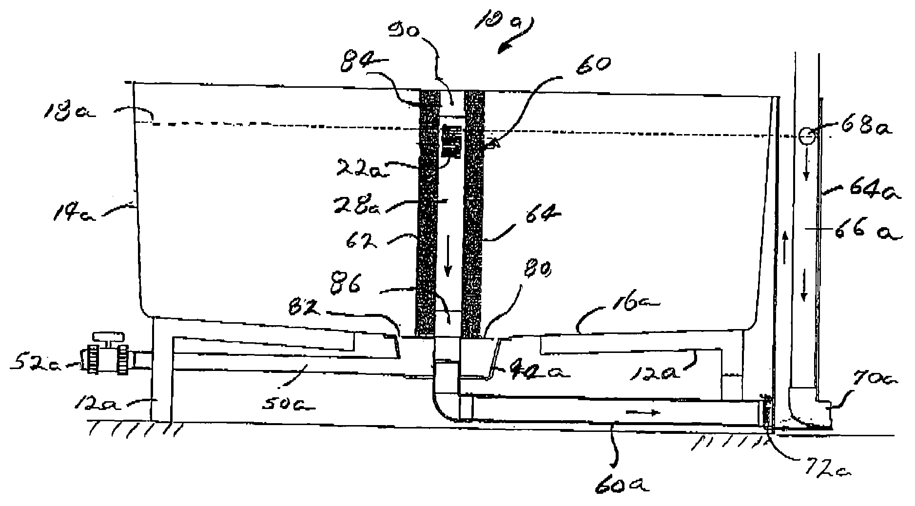
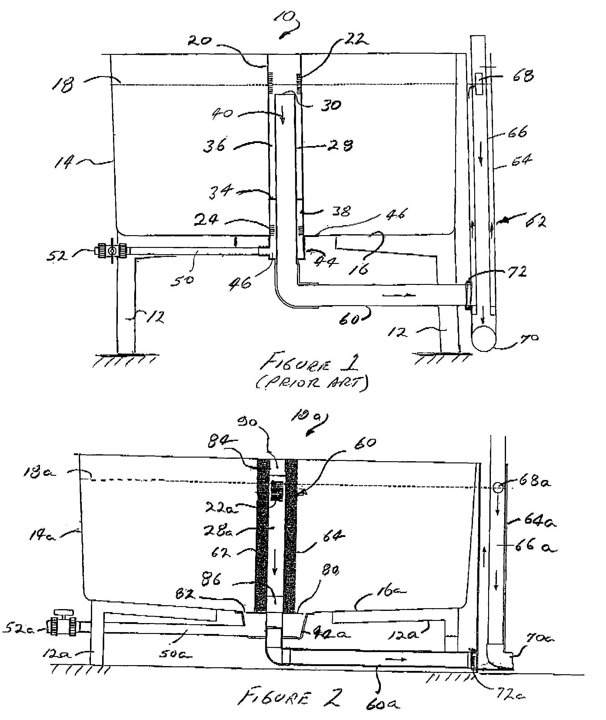
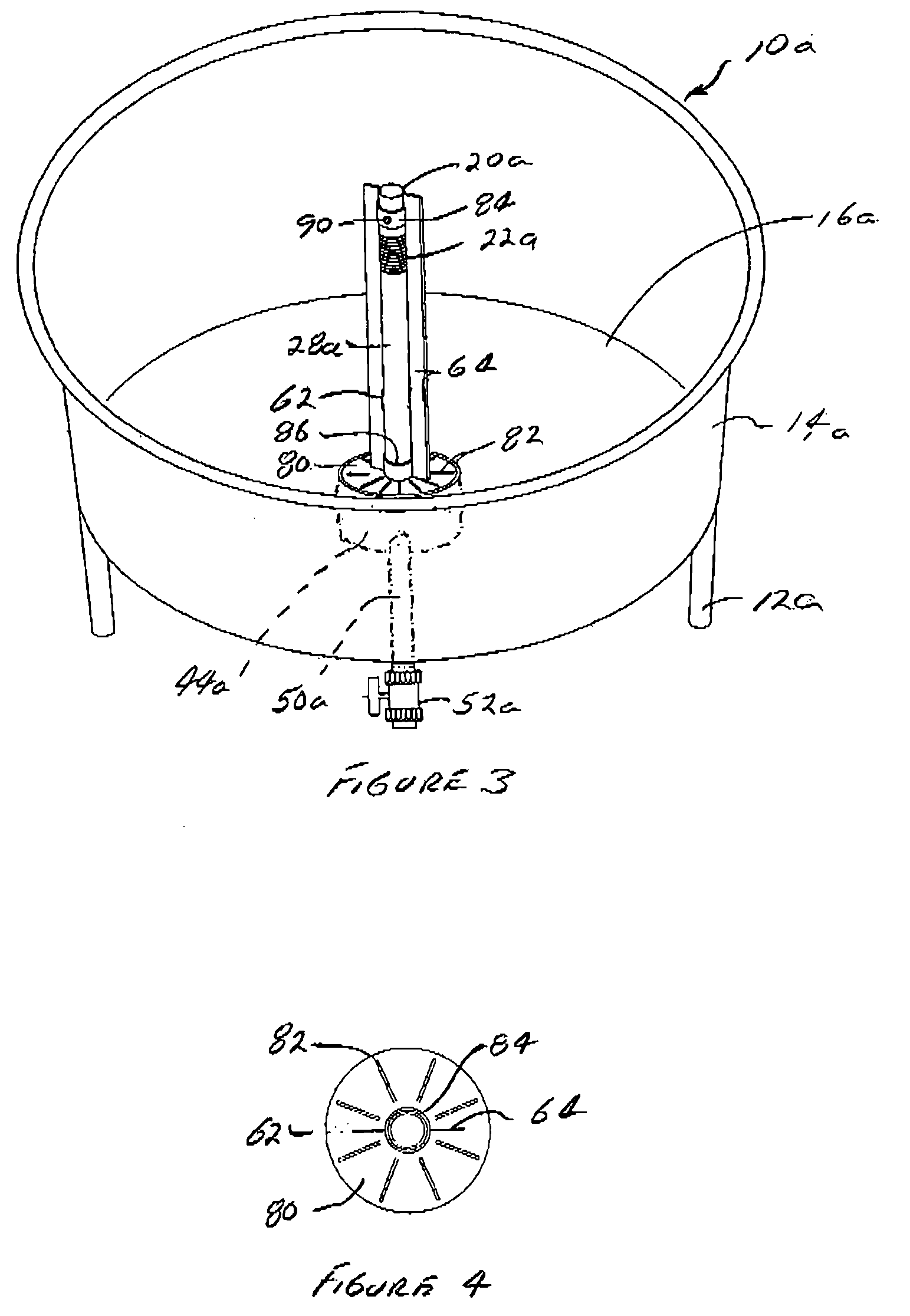
[0031]With respect to FIGS. 2-4, structural features being common relative to those in FIG. 1 are noted with the letter “a”.
[0032]To take advantage of the stronger “tea cup effect” of the axial flow design in higher flow configurations, consideration was given to attempting to lessen the formation of vortices. The most effective preferred configuration has been the addition of an anti-vortex fin assembly 60, preferably with two relatively narrow vertical fins 62, 64 along the sides of the central clarified water manifold 28a extending the entire depth of the water manifold as seen in FIGS. 2-4. This new anti-vortex axial flow configuration allows for a strong “tea cup effect” while minimizing the re-suspension of settled solids. It creates a “quiet zone” at the base of the vertical clarified water manifold 28a adjacent tank floor 16, where solids can be easily removed from the fish tank.
[0033]A second aspect of the invention allows passive removal of settled solid particles into an ...
PUM
| Property | Measurement | Unit |
|---|---|---|
| Length | aaaaa | aaaaa |
| Height | aaaaa | aaaaa |
Abstract
Description
Claims
Application Information