Tank having a piston pressurized by hot gas
a technology of hot gas and cylinder, which is applied in the direction of liquid transferring devices, instruments, machines/engines, etc., can solve the problems of complex implementation of the telescopic arrangement of the bladder and the inability to use the metal bladder system in the tank that is pressurized
- Summary
- Abstract
- Description
- Claims
- Application Information
AI Technical Summary
Benefits of technology
Problems solved by technology
Method used
Image
Examples
first embodiment
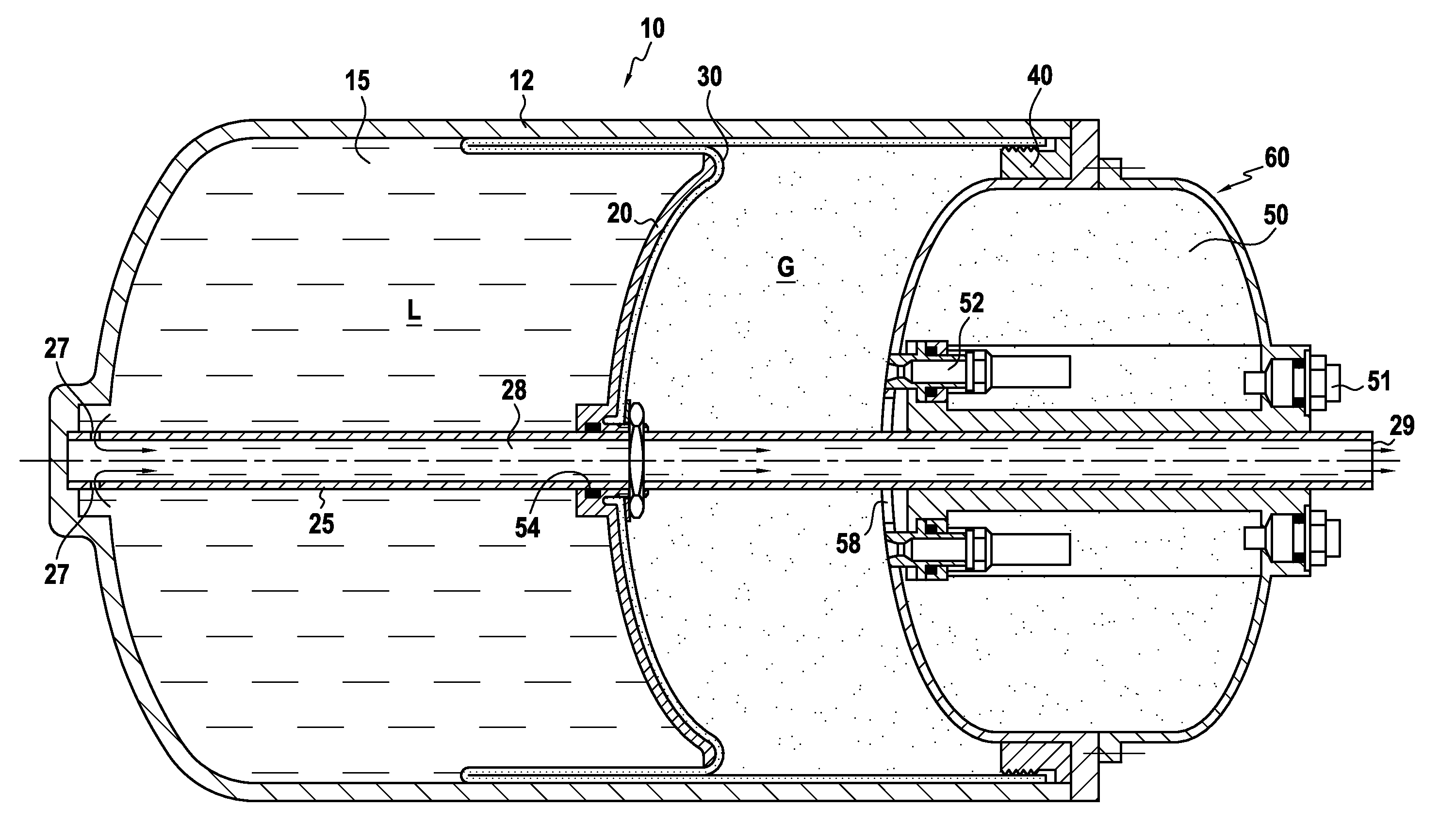
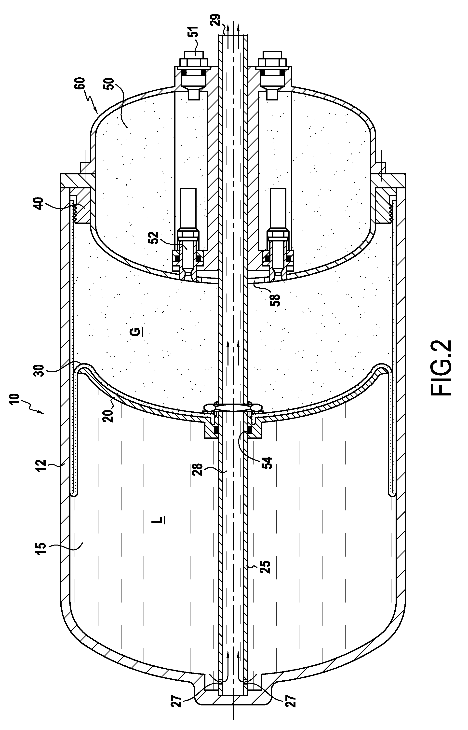
[0030]FIG. 1 shows a tank 10 in accordance with the invention.
[0031]The tank 10 is defined by a wall 12 of generally cylindrical shape.
[0032]It has a piston 20 suitable for moving along a shaft 25, the piston thus co-operating with the wall 12 to define a variable-volume chamber 15 that is filled with a liquid propellant component L at ambient temperature, i.e. at about 20° C.
[0033]In the embodiment described, the variable-volume chamber is adjacent to a gas generator 60.
[0034]In accordance with the invention, the tank 10 includes a deformable elastomer membrane 30 pressed against a face of the piston 20 that is outside the chamber 15.
[0035]This elastomer membrane 30 also provides sealing between the piston 20 and the wall 12.
[0036]In the embodiment described, the membrane 30 is held at the end of the tank 10 by annular fastener means 40 that hold the membrane against the wall 12.
[0037]Sealing between the shaft 25 and the piston 20 is provided by means of an O-ring gasket referenced...
second embodiment
[0053]FIG. 4 shows a tank 100 in accordance with the invention.
[0054]This tank 100 is almost identical to the tank 10 described with reference to FIGS. 1 to 3.
[0055]However in this embodiment, the liquid is delivered in the travel direction of the piston 20.
[0056]Consequently, the delivery duct 28 has only one open end 29, and that end is located close to the opening 27 for liquid ingress.
[0057]Preferably, the delivery duct 28 is closed off immediately behind the opening 27. It is no more than a cavity.
[0058]Furthermore, the tank 100 presents an opening 110 in its end wall facing the open end 27 of the duct 28.
[0059]In the embodiment described, the O-ring gasket 54 closes the inlet 27 to the duct 28 when the piston 10 reaches the end of its stroke.
third embodiment
[0060]FIG. 5 shows a tank 200 in accordance with the invention.
[0061]The tank 200 is practically identical to the tanks 10 and 100 described with reference to FIGS. 1 to 4.
[0062]However, in this embodiment, the liquid is delivered in both directions, both ends 29 of the delivery duct 28 being open.
PUM
| Property | Measurement | Unit |
|---|---|---|
| Temperature | aaaaa | aaaaa |
Abstract
Description
Claims
Application Information
 - Generate Ideas
- Intellectual Property
- Life Sciences
- Materials
- Tech Scout
- Unparalleled Data Quality
- Higher Quality Content
- 60% Fewer Hallucinations
Browse by: Latest US Patents, China's latest patents, Technical Efficacy Thesaurus, Application Domain, Technology Topic, Popular Technical Reports.
© 2025 PatSnap. All rights reserved.Legal|Privacy policy|Modern Slavery Act Transparency Statement|Sitemap|About US| Contact US: help@patsnap.com


