Alternating current motor drive circuit and electric vehicle drive circuit

a technology of electric vehicle and drive circuit, which is applied in the direction of motor/generator/converter stopper, electric generator control, dynamo-electric converter control, etc., can solve the problems of difficult circuit downsizing, circuit becomes larger, circuit becomes larger, etc., and achieves simple circuit configuration, reduced cost, and reduced cost. the effect of cost and weigh

Active Publication Date: 2009-08-20
NAT UNIV CORP NAGAOKA UNIV TECH +1
View PDF4 Cites 33 Cited by
  • Summary
  • Abstract
  • Description
  • Claims
  • Application Information

AI Technical Summary

Benefits of technology

[0012]According to the above-described inventions, as it is possible to bidirectionally convert power of the direct current power source into a direct current link, it is possible to omit or downsize a reactor required for a conventional chopper, therefore enabling an achievement of a reduction in cost, size and weight of the drive circuit.
[0013]Further, in an application in which there is a case of causing the current source rectifier to regenerate power to the alternating current generator, it is possible to realize the drive circuit with a simple circuit configuration. Also, as the number of switches to be passed in a path through which a current flows is as small as two in the rectifier, a power conversion is efficient, too.
[0014]Still further, in an application not causing the current source rectifier to regenerate power to the alternating current generator, it is possible to form a still simpler circuit.
[0015]In addition, it being possible to downsize the alternating current generator or the alternating current motor, thereby reducing the total size of a drive system including them.
[0016]Finally, according to the invention, although in an electric vehicle drive circuit of a hybrid vehicle or the like, it is necessary to mount the circuit in a limited space, no large reactor is needed in the circuit of the invention, and thus it is possible to mount a circuit which produces a high output, which makes it possible to improve an acceleration and deceleration performance of an electric vehicle.

Problems solved by technology

In the meantime, in FIG. 10, a large-capacity version of the capacitor 13 is needed for smoothing a direct current, it is difficult to downsize the circuit.
Also, a reactor L1 is needed in the direct current chopper 12, there is a problem in that the circuit becomes larger due to this too.
Also, a reactor L1 is needed in the direct current chopper circuit 32, there is a problem in that the circuit becomes larger due to this too.

Method used


Image

  • Alternating current motor drive circuit and electric vehicle drive circuit
  • Alternating current motor drive circuit and electric vehicle drive circuit
  • Alternating current motor drive circuit and electric vehicle drive circuit

Examples


Embodiment Construction

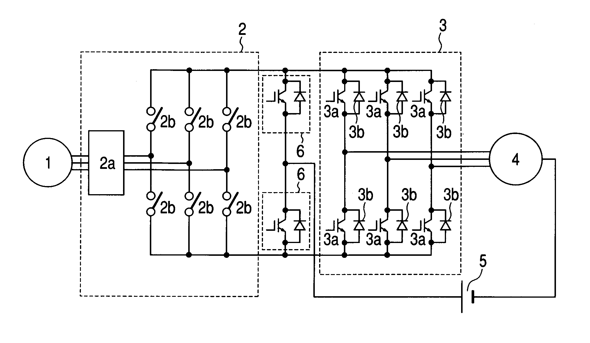
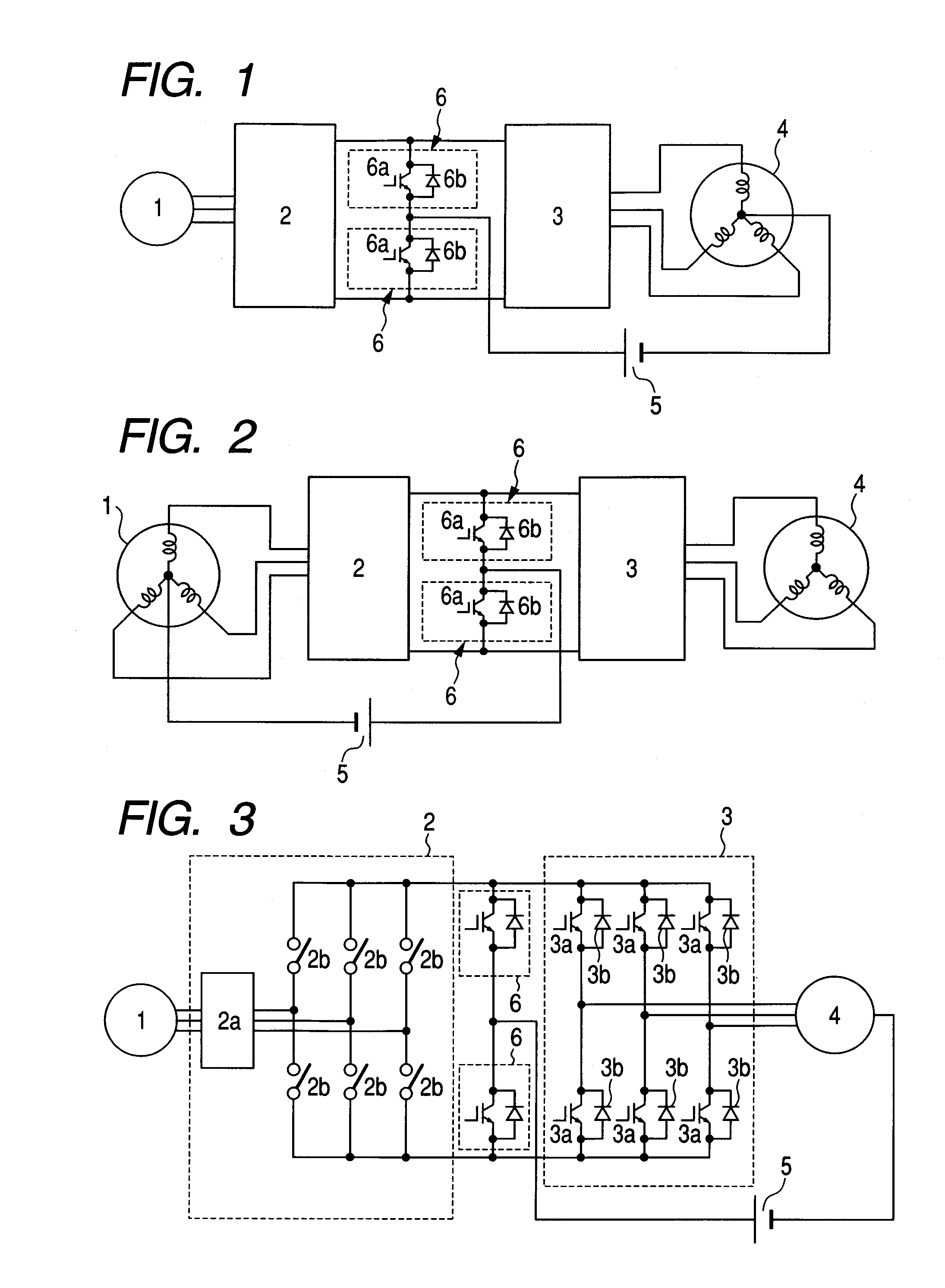
[0031]FIG. 1 is a configuration diagram showing an embodiment of the invention. As shown in FIG. 1, in this example, a current source rectifier 2 and a voltage source inverter 3 are connected to an output of a three-phase alternating current generator 1, and an alternating current motor 4 is driven by the output thereof. The combination of the current source rectifier 2 and voltage source inverter 3 being called, for example, an Indirect Matrix Converter, as disclosed in “Technical Trends of Direct AC / AC Converters”, Institute of Electrical Engineers of Japan Transactions on Industry Application, Vol. 126, No. 9, pp. 1161-1170, by employing a current source rectifier as a rectifier, a need for a large part, such as the capacitor 13 shown in FIG. 10, is eliminated.

[0032]Also, two arms 6 having switching elements 6a connected in inverse parallel to diodes 6b are connected in series to an output of the rectifier 2. Furthermore, a positive terminal of a storage battery 5 is connected to...


PUM


Abstract

A current source rectifier is provided at an output of an alternating current generator, an alternating current motor is connected to an output of the rectifier via a voltage source inverter, furthermore, two arms having switching elements connected in inverse parallel to diodes are connected to the output of the rectifier, and one terminal of a direct current power source capable of a power supply and absorption is connected to a midpoint between the arms, while the other terminal thereof is connected to a neutral point of motor coils or generator coils, thereby eliminating a need for a large volumetric reactor in a direct current chopper, achieving a downsizing of the circuit.

Description

BACKGROUND OF THE INVENTION[0001]The present invention relates to an alternating current motor drive circuit which drives an alternating current motor, using an alternating current generator and a direct current power source capable of a power supply and absorption, and to an electric vehicle drive circuit using the drive circuit.[0002]FIG. 10 is a circuit diagram showing a first conventional example of an alternating current motor drive circuit as shown in JP-A-2004-112883, in which a three-phase output of an alternating current generator M2 is converted into a direct current by a voltage source rectifier 31 in which arms having switching elements connected in inverse parallel to diodes are bridge-connected, and the voltage of the direct current is smoothed by a capacitor 13. Also, a direct current chopper 12 is provided between the smoothed direct current (connection points N1 and N2) and a battery B, and a power exchange between them is carried out. Furthermore, using the direct ...

Claims


Application Information

Patent Timeline
Patent Type & Authority Applications(United States)
IPC IPC(8): H02P27/00B60L50/15H02M7/48H02P27/06
CPCB60L11/18B60L2210/20B60L2210/42H02M7/217Y02T10/725H02P27/04Y02T10/642Y02T10/7005Y02T10/7241H02P9/48B60L50/60Y02T10/64Y02T10/72Y02T10/70
Inventor ITOH, JUN-ICHIIWAHORI, MICHIOGEKINOZU, MASAKAZU
Owner NAT UNIV CORP NAGAOKA UNIV TECH
Why Eureka
Try Eureka