Laser obstacle avoidance apparartus

a laser and obstacle avoidance technology, applied in distance measurement, surveying and navigation, instruments, etc., can solve the problems of complex and expensive laser radar and processor, and achieve the effect of simple and inexpensive laser obstacle avoidan

Inactive Publication Date: 2006-11-07
UNITED STATES OF AMERICA THE AS REPRESENTED BY THE SEC OF THE ARMY
View PDF1 Cites 7 Cited by
  • Summary
  • Abstract
  • Description
  • Claims
  • Application Information

AI Technical Summary

Benefits of technology

[0005]Accordingly, one object of the present invention is to provide a simple and inexpensive laser obstacle avoidance device.

Problems solved by technology

The disadvantage is that both the laser radar and the processor are complex and expensive.

Method used


Image

  • Laser obstacle avoidance apparartus
  • Laser obstacle avoidance apparartus
  • Laser obstacle avoidance apparartus

Examples


Embodiment Construction

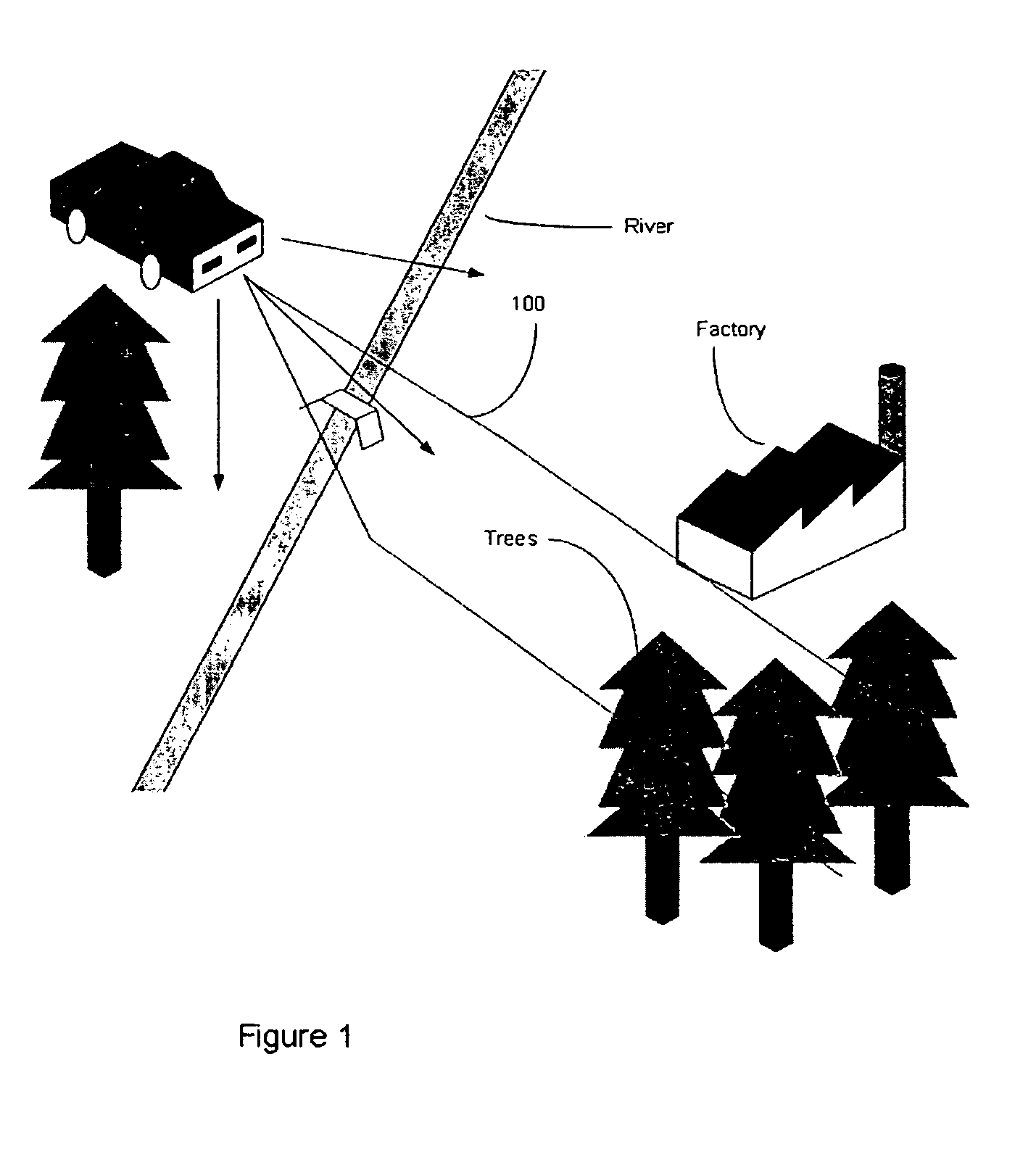
[0014]As depicted in FIG. 1, the operator of a combat vehicle encounters many natural and man-made obstacles particularly when he drives across unfamiliar terrain. In combat, he or she is required to make quick decisions to avoid these hazards while slowing down as little as possible. When this occurs at night, the change in environmental cues places additional demands on the vehicle operator, who is using a passive night vision devices as a driving aid. The LOAD sensor is intended to assist the operator by scanning the terrain ahead of the vehicle by sending out laser signals 100, detecting sudden range changes that could represent a hazard and providing the driver with a warning on his passive night vision imaging display.

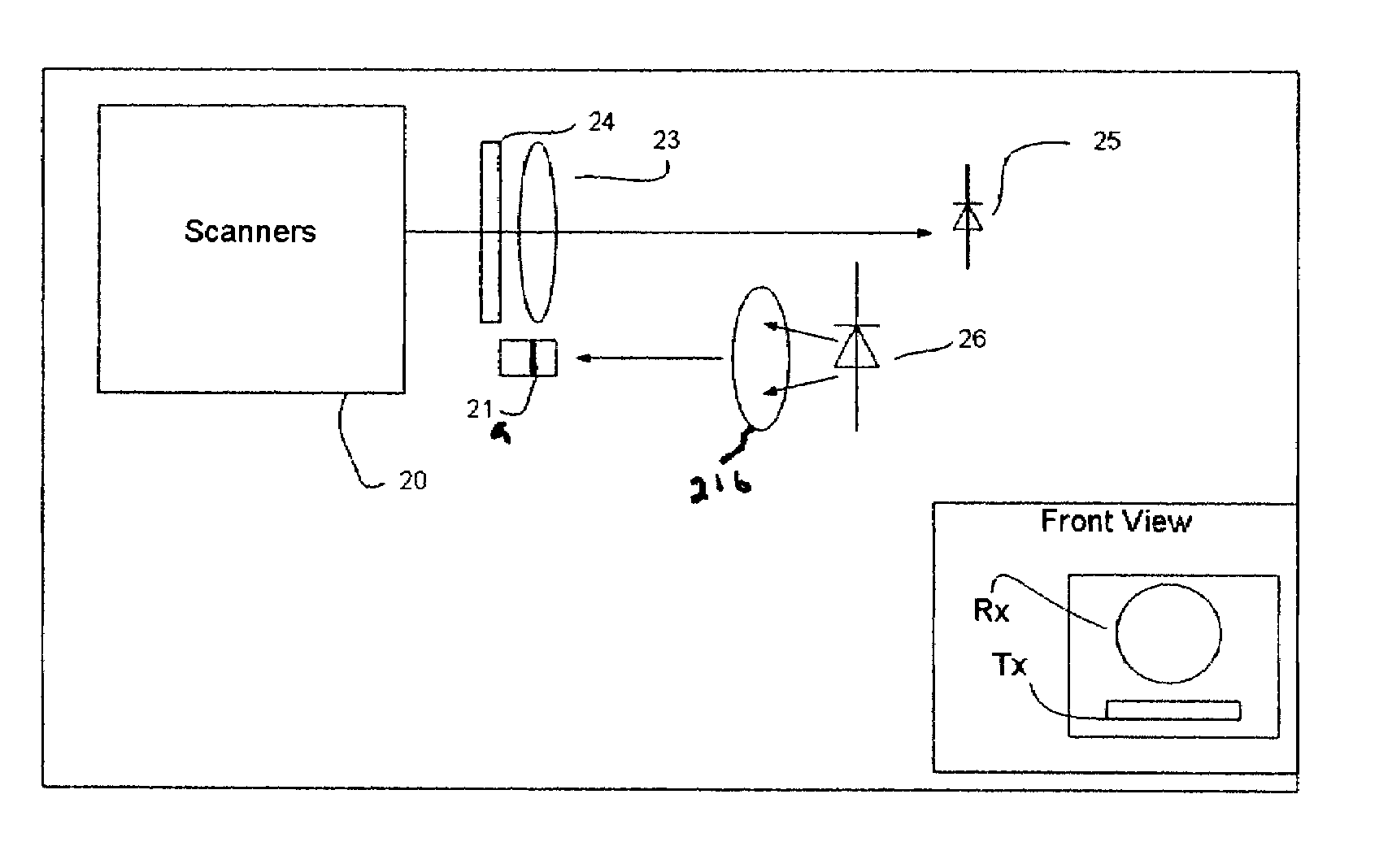
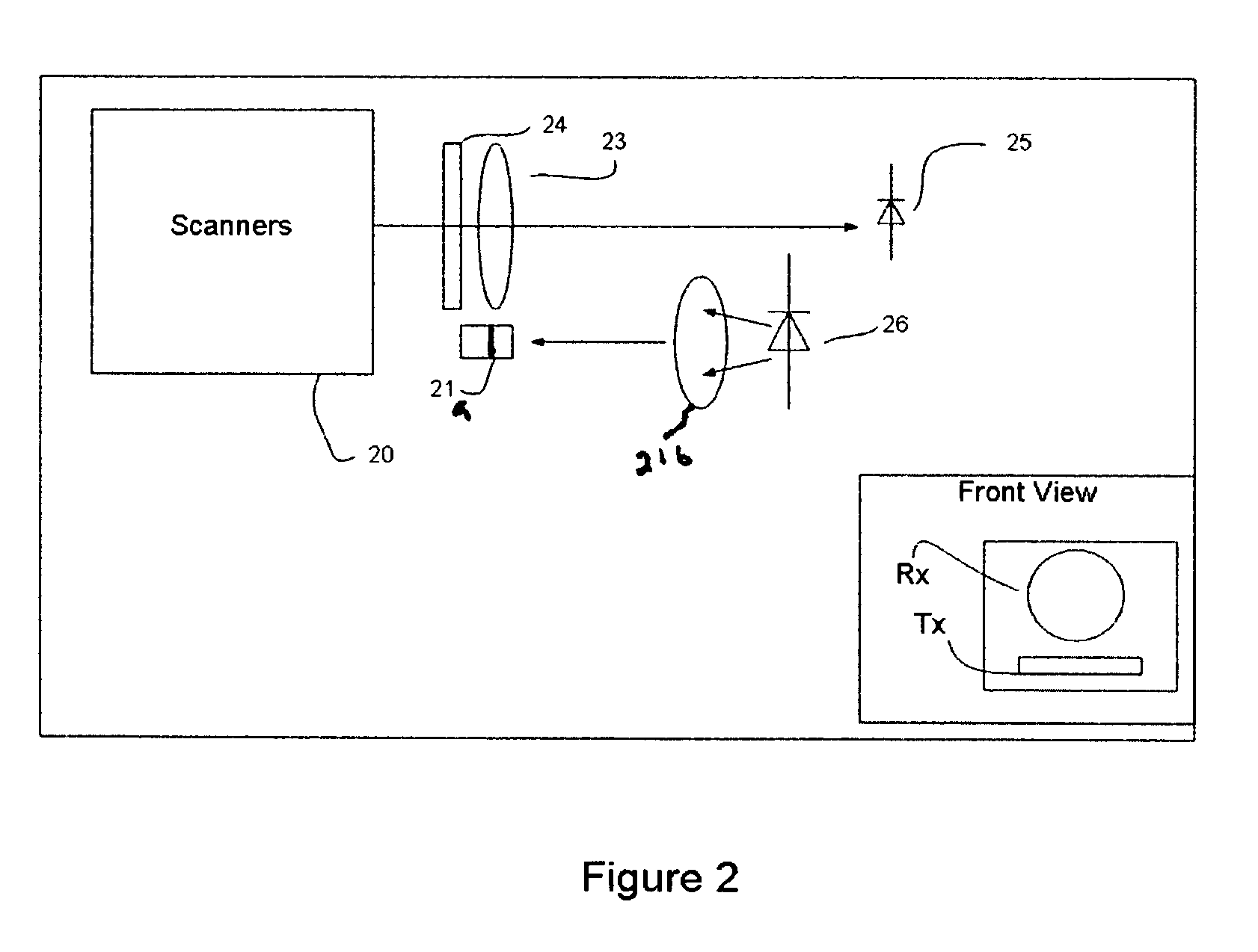
[0015]The laser obstacle avoidance device (LOAD) sensor of the present invention is intended to be a warning aid to operators of vehicles when driving at night using passive night vision sensors. The sensor will allow drivers to more readily identify hazards and ...


PUM


Abstract

The laser obstacle avoidance device of the present invention includes an optical head which includes a laser source which produces a laser signal, crossed cylindrical lenses and through which the laser signal is transmitted, a transceiver including a receiving lens through which a reflected laser signal is received by the transceiver, a receiver and a line filter through which the reflected laser signal is filtered, and scanners which receive the reflected laser signal; and control electronics optically connected to the optical head, wherein the control electronics comprise scanner driver electronics, range processor electronics, power converters, and a display all which produce an x-y display of the terrain scanned by the laser signal wherein the X-axis is driven by a scanner position output and the Y-axis by range data. The system was designed to avoid hazards with emphasis simplicity and low cost. The device has been employed in the field to collect data from natural and man-made objects. A simple, single scan line, range discontinuity detection program has been written and tested. The next step in the process is to interface the output of the processor with driver's display indicating the location of the potential hazard for the operator's closer scrutiny.

Description

GOVERNMENT INTEREST[0001]The invention described herein may be manufactured, used, sold, imported, and / or licensed by or for the Government of the United States of America.FIELD OF INTEREST[0002]This invention generally relates to light detection and ranging systems, particularly systems capable of detecting obstacles in the path of a moving ground vehicle.BACKGROUND OF THE INVENTION[0003]Laser based obstacle avoidance systems have relied on imaging techniques in which the range is measured to every pixel in a field of view ahead of the vehicle. The result is a three dimensional image requiring intensive digital image processing to locate both obstacles and a clear path for the vehicle to traverse. Using this sensor the vehicle can autonomously negotiate unfamiliar terrain. The disadvantage is that both the laser radar and the processor are complex and expensive.[0004]Accordingly, there is a need to have a simple and inexpensive laser obstacle avoidance system. The present invention...

Claims


Application Information

Patent Timeline
Patent Type & Authority Patents(United States)
IPC IPC(8): G01C3/08
CPCG01C3/08
Inventor LEI, JONATHAN S.SCHILLING, BRADLEY W.BARR, DALLAS N.NETTLETON, JOHN E.QUARLES, MICHAEL M.
Owner UNITED STATES OF AMERICA THE AS REPRESENTED BY THE SEC OF THE ARMY
Why Eureka
Try Eureka