Touch-sensitive interface device and method

US20090207147A1Inactive Publication Date: 2009-08-20LEGRAND SNC

Image

  • Touch-sensitive interface device and method
  • Touch-sensitive interface device and method
  • Touch-sensitive interface device and method

Examples


Embodiment Construction

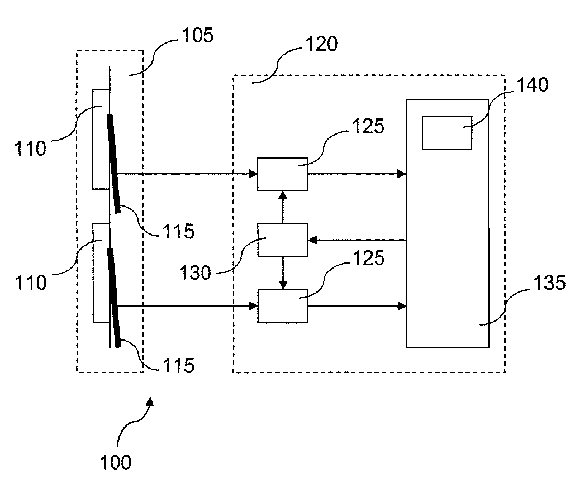
[0046]It is seen, in FIG. 1, that, in one particular embodiment, the device 100 includes, on the one hand, a keypad 105 including keys 110 and voltage generator means 115 and, on the other hand, an electronic interface 120 including voltage comparator means 125, a means 130 for modifying threshold voltages applied to the voltage comparator means 125, and a central processor unit card 135.

[0047]The central processor unit card 135 includes a power supply unit 140. The central processor unit is, for example, based on a microcontroller, a digital signal processor (DSP) or a component including a processor.

[0048]The voltage generator means 115 are adapted to generate a voltage when they are mechanically deformed. The voltage generator means 115 preferably include piezoelectric elements mechanically associated with the keys of the keypad in a manner that is known in itself. For example, the keypad 105 consists of a block consisting of a sandwich of a number of materials, including the mat...


PUM


Abstract

A touch-sensitive interface device includes:—a touch-sensitive keypad including elements for generating a voltage as the effect of a mechanical deformation, and—a signal processing electronic interface adapted to detect pressing and / or releasing of a voltage generator elements and to go to standby after the pressing and / or the releasing of each voltage generator elements. The voltage generator elements preferably includes a piezoelectric element. In embodiments, the electronic interface includes at least one voltage comparator device, the generation of a parameterable threshold voltage to which the voltage comparator device compares the voltage at the terminals of a voltage generator element, and a card including a central processor unit and its power supply unit. The parameterable threshold voltage can be increased or decreased to detect positive and negative peaks of at least one voltage generator elements respectively caused by pressing or releasing at least one voltage generator elements.

Description

FIELD OF THE INVENTION[0001]The present invention concerns a touch-sensitive interface device and method. It applies in particular to guaranteeing the autonomy of electronic products provided with a touch-sensitive man-machine interface (MMI) that are not connected to a permanent power supply.TECHNOLOGICAL BACKGROUND[0002]Electronic solutions dedicated to touch-sensitive interfaces consume too much current to guarantee an autonomy of at least two years to products that are not connected to a permanent power supply.[0003]Nomadic electronic products provided with a touch-sensitive interface that are not connected to a permanent power supply, such as portable digital music players, mobile telephones, personal digital assistants and geo-location systems, generally use rechargeable batteries. So-called “capacitive” touch-sensitive interface technologies offer very low consumption but cannot always enable a product to function normally for at least two years without intervention such as r...

Claims


Application Information

Patent Timeline
20 Aug 2009
Publication
US20090207147A1
IPC
G06F3/041
CPC
G06F1/3215; G06F1/3262; Y02B60/32; G06F3/0414; Y02B60/1257; G06F1/3271; Y02D10/00; Y02D30/50
Inventors
PERROT, ALEXANDRE; RIGOLLET, SEBASTIEN