
Liquid jet head and a liquid jet apparatus

Inactive Publication Date: 2009-08-20
SEIKO EPSON CORP
View PDF1 Cites 2 Cited by
  • Summary
  • Abstract
  • Description
  • Claims
  • Application Information

AI Technical Summary

Benefits of technology

[0008]The present invention is devised in view of such a circumstance, and an object of the present invention is to provide a liquid jet head and a liquid jet apparatus capable of effectively dissipating heat from a driving circuit, achieving miniaturization and low cost for the driving circuit, and improving the durability of the driving circuit, thereby improving liquid ejection characteristics.
[0010]According to this aspect, the heat of the driving circuit can be allowed to be thermally conductive to the flow passage member partitioning the liquid instruction passage and the flow passage member can be cooled (heat-dissipated) by the liquid flowing in the liquid introduction passage. With such a configuration, it is possible to prevent the driving circuit from being broken down due to the heat. Moreover, it is possible to reduce the size of the driving circuit without increase in the driving circuit and thus reduce the cost. Furthermore, it is possible to improve durability of the driving circuit by suppressing the lifetime of the driving circuit from being shortened due to the heat and improve a liquid ejection characteristic and an ability in continuous ejection of a liquid.
[0011]It is preferable that the flow passage member is formed of a material having thermal conductivity higher than that of the case head. Accordingly, it is possible to effectively suppress the heat dissipation of the driving circuit by effectively allowing the heat of the driving circuit to be thermally conductive to the flow passage member.
[0014]According to such an aspect, it is possible to realize the liquid jet apparatus that is improved in reliability and can be manufactured at low cost.

Problems solved by technology

However, since only the driving circuit mounted on the flexible printed circuit board is able to dissipate heat from the driving circuit, the heat dissipation ability is restrained.
When a circuit loss exceeds the heat dissipation ability, the driving circuit may be destroyed by heat.
Moreover, since a large heat dissipation area is required for securing the heat dissipation properties, a problem may occur in that it is difficult to reduce the size of the driving circuit.
These problems are similarly found in other liquid jet heads ejecting liquid other than ink as well as the ink jet recording head.

Method used


Image

  • Liquid jet head and a liquid jet apparatus
  • Liquid jet head and a liquid jet apparatus
  • Liquid jet head and a liquid jet apparatus

Examples


first embodiment

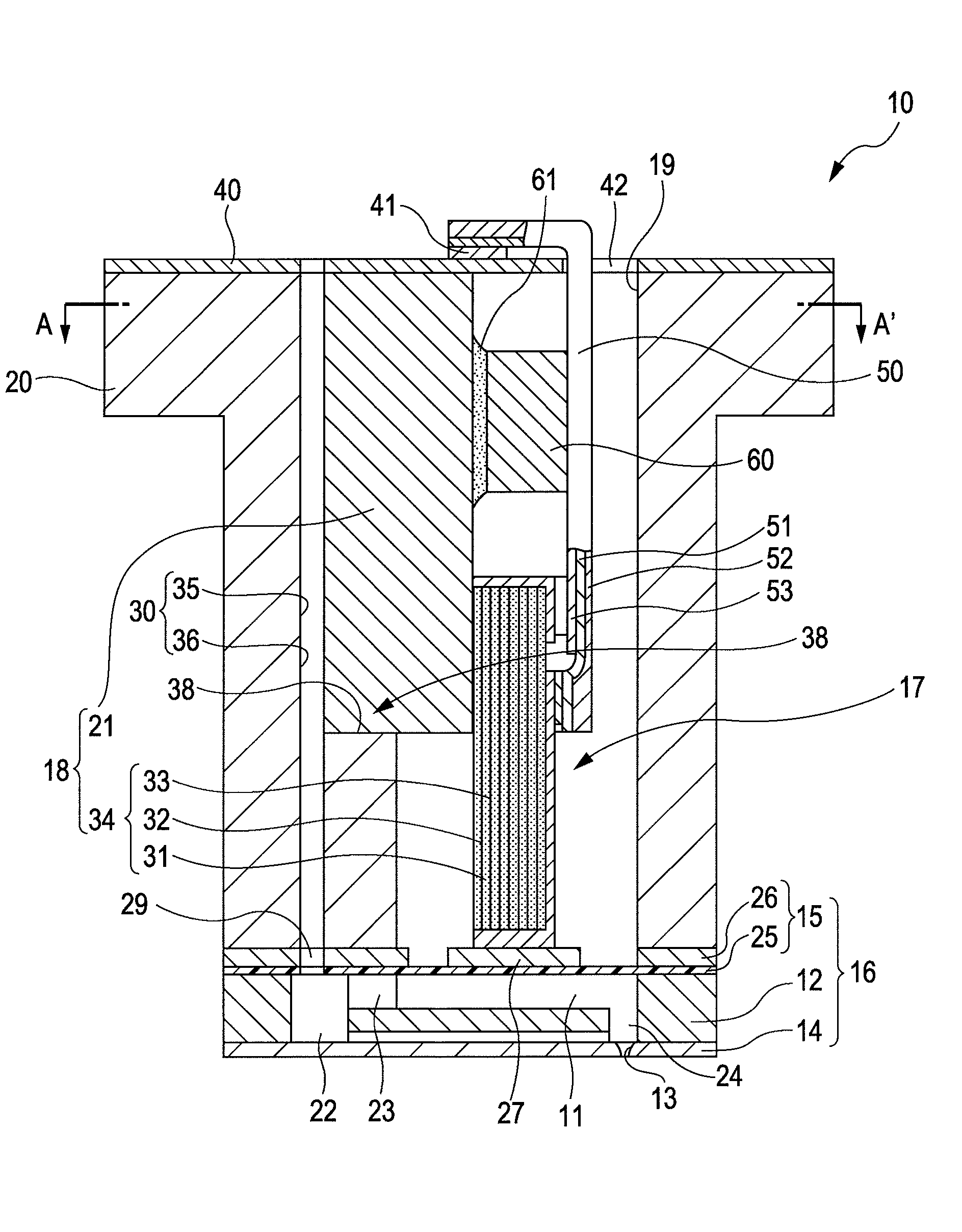
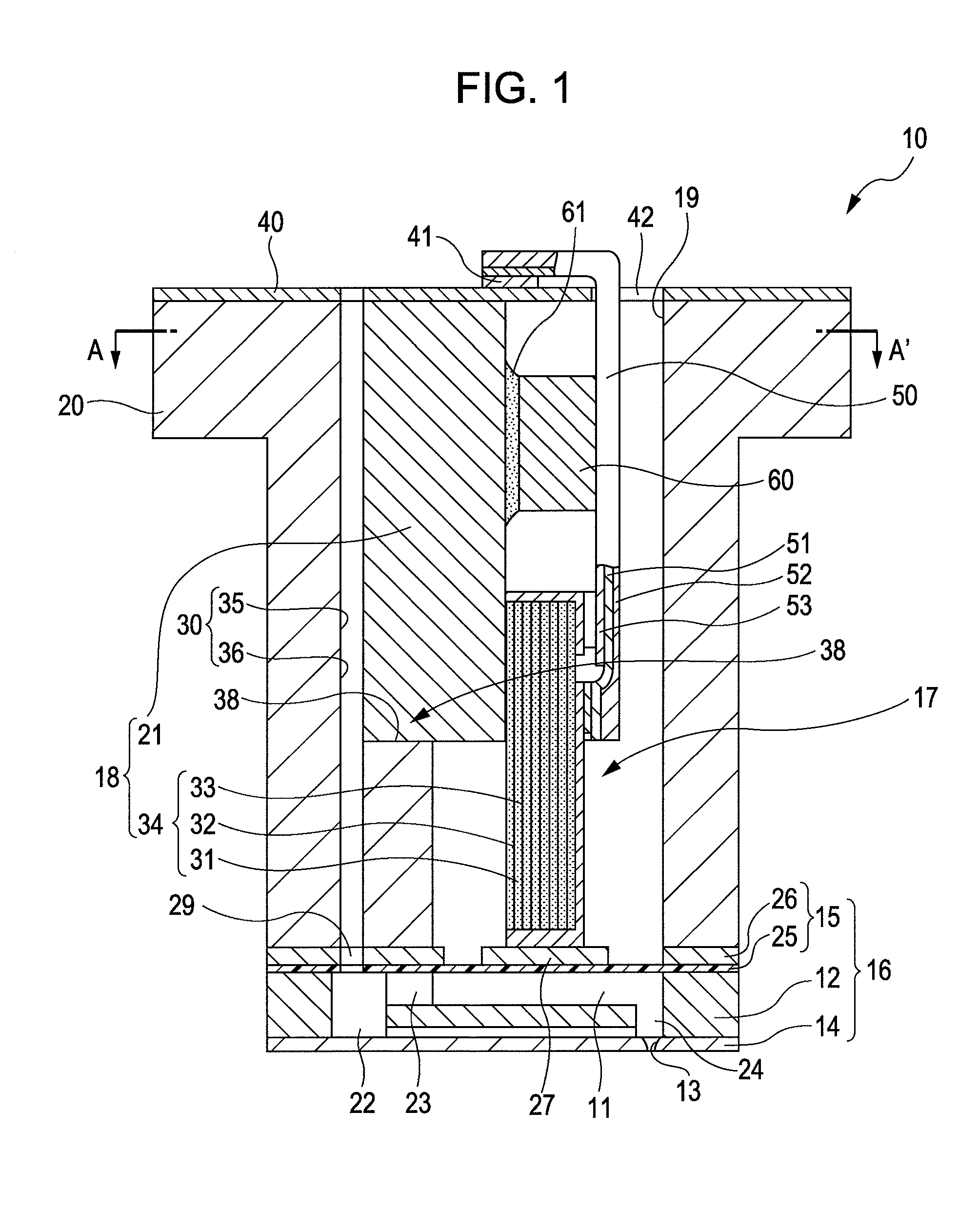
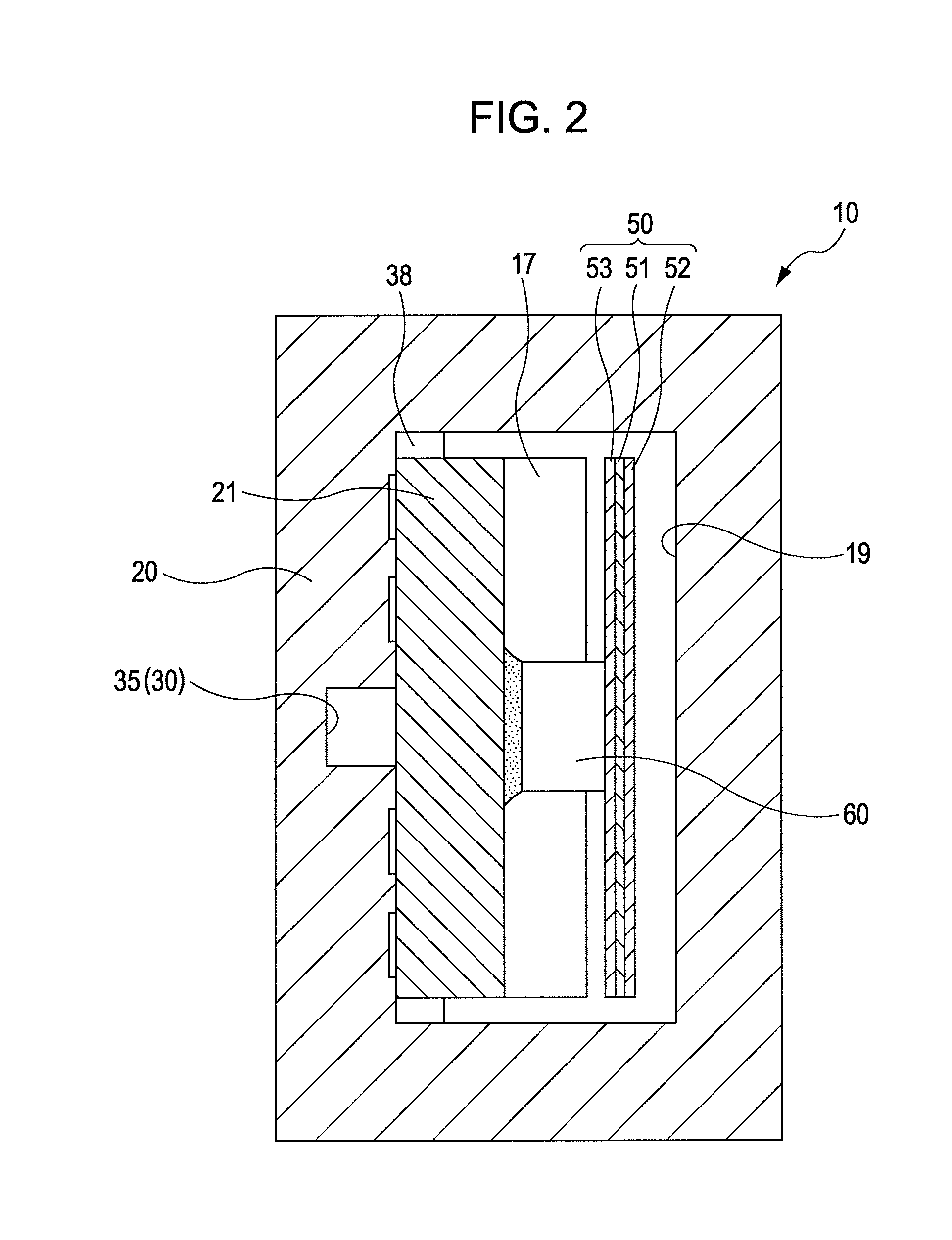
[0038]FIG. 1 is a sectional view illustrating an ink jet recording head that is an example of a liquid jet head according to a first embodiment of the invention. FIG. 2 is a sectional view taken along the line A-A′ in FIG. 1.

[0039]As illustrated in the drawings, an ink jet recording head 10 has a flow passage unit 16 that is provided with a flow passage forming board 12 having a plurality of pressure generation chambers 11, a nozzle plate 14 in which a plurality of nozzle openings 13 is formed to individually communicate with the pressure generation chambers 11, and a vibration plate 15 that is provided on a surface of the flow passage forming board 12 opposite to the nozzle plate 14. In addition, the ink jet recording head is provided with a piezoelectric element unit 18 that has piezoelectric elements 17 being provided on an area of the vibration plate 15 and individually corresponding to the pressure generation chambers 11, a case head 20 that has an accommodation portion 19 bein...

second embodiment

[0060]FIG. 3 is a sectional view illustrating an ink jet recording head as an example of a liquid jet head according to a second embodiment of the invention. FIG. 4 is a sectional view taken along the line B-B′ of FIG. 3. The same reference numerals are given to the same constituent elements as those according to the above-described first embodiment, and repeated description is omitted.

[0061]As illustrated in the drawings, an ink jet recording head 10A according to this embodiment includes a case head 20A and a flow passage member 21A accommodated in an accommodation portion 19 of the case head 20A. The case head 20A is provided with only a communication hole 36 on a side of a flow passage forming board 12. A step portion 38 of the case head 20A is formed up to a location where the bottom surface of the communication hole 36 is opened. The flow passage member 21A fixed to the step portion 38 is provided with a through-hole 35A communicating the communication hole 36. An ink introduc...


PUM


Abstract

A liquid jet head includes: a pressure generation chamber 11 communicating with a nozzle opening 13 ejecting a liquid; a piezoelectric element 17 causing pressure change inside the pressure generation chamber 11; a case head 20 having an accommodation portion 19 accommodating the piezoelectric element 17; and a flexible printed board 50 having a driving circuit 60 mounted thereon and connected to the piezoelectric element 17 to drive the piezoelectric element 17. The accommodation portion 19 of the case head 20 is provided with a flow passage member 21 holding a base end portion of the piezoelectric element 17 and being connected to the driving circuit 60 in a thermally conductive manner, the case head 20 is provided with a liquid introduction passage 30 for supplying the liquid to the pressure generation chamber 11, and the flow passage member 21 partitions a part of at least a wall surface of the liquid introduction passage 30.

Description

BACKGROUND OF THE INVENTION[0001]The entire disclosure of Japanese Patent Application No. 2008-015890, filed Jan. 28, 2008 is incorporated by reference herein.FIELD OF THE INVENTION[0002]The present invention relates to a liquid jet head and a liquid jet apparatus capable of ejecting a liquid from nozzle openings, and particularly to an ink jet recording head and an ink jet recording apparatus capable of ejecting ink.INVENTION OF THE RELATED ART[0003]As a typical example of a liquid jet head, for example, there is known an ink jet recording head that ejects ink droplets from nozzle openings by using pressure change caused by displacement of piezoelectric elements. Specifically, as disclosed in JP-A-2004-74740, an ink jet recording head is known which includes: a flow passage unit that has a flow passage forming plate having therein pressure generation chambers, which individually communicate with nozzle openings, and a vibration plate provided on one surface of the flow passage form...

Claims


Application Information

Patent Timeline
IPC IPC(8): B41J2/045
CPCB41J2/14233B41J2202/08
Inventor ITO, SUKEHIRO
Owner SEIKO EPSON CORP
Learn More