Method for Determining Scattered Disparity Fields in Stereo Vision

a technology of stereo vision and disparity field, applied in image analysis, image enhancement, instruments, etc., can solve the problems of klt technique not exploiting the fundamental, subject to errors or inaccuracy, etc., and achieve the effect of improving the quality of extracted disparity field and accurate results

Active Publication Date: 2009-08-20
TELECOM ITALIA SPA
View PDF10 Cites 196 Cited by
  • Summary
  • Abstract
  • Description
  • Claims
  • Application Information

AI Technical Summary

Benefits of technology

[0011]The Applicant found that, by suitably modifying the KLT method in order to take into account information pertaining to the fundamental matrix, which can be computed through a calibration process, it is possible to improve the quality of the extracted disparity field. In particular, the Applicant found that, by modifying the point tracking process in order to take into account the fundamental matrix, but without setting absolute constraints, it is possible to affect at will the process, in order to compensate for errors in calibrating the system.
[0012]In particular, the Applicant found that, by allowing the arrangement to deviate from the epipolar straight line, through the introduction, in the KLT technique cost function, of a term proportional to the square of the distance between epipolar line and searched point, it can be possible to obtain accurate results also when there is an approximate calibration. The thereby obtained results can be better both than those which can be obtained by applying the original KLT technique, and than those which can be obtained by constraining the identified points to rest only on the epipolar straight lines.

Problems solved by technology

The Applicant observed that the KLT technique does not exploit the fundamental matrix knowledge, which is often available above all in case of two or more cameras.
However, the calibration is typically obtained through estimations and is therefore subjected to errors or inaccuracies.

Method used


Image

  • Method for Determining Scattered Disparity Fields in Stereo Vision
  • Method for Determining Scattered Disparity Fields in Stereo Vision
  • Method for Determining Scattered Disparity Fields in Stereo Vision

Examples


Embodiment Construction

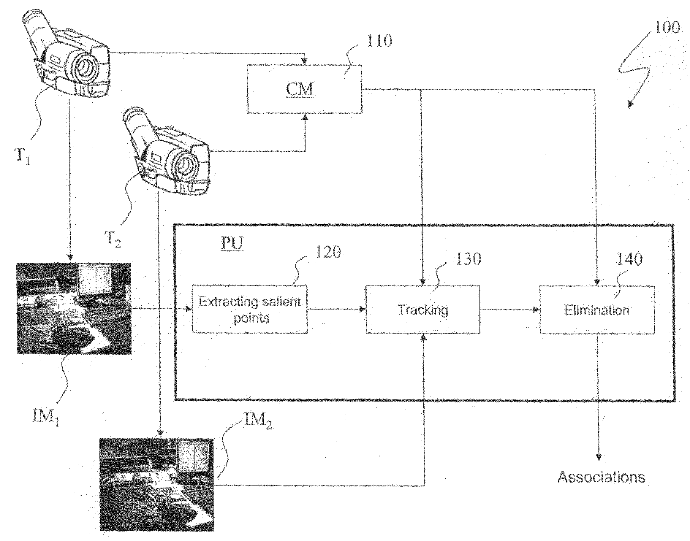
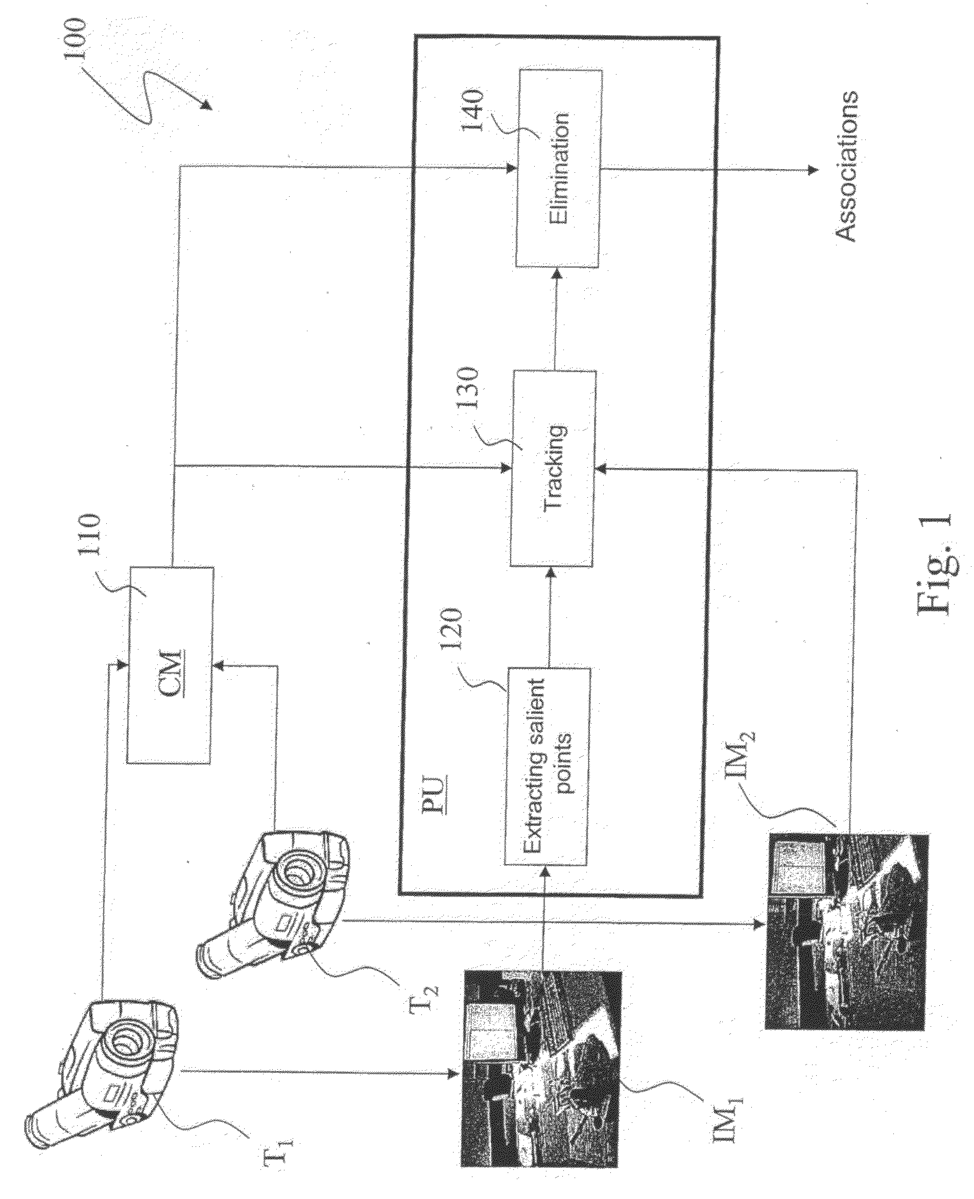
[0024]With reference to FIG. 1, 100 designates as a whole a system for video shooting with many cameras. In particular, the system 100 is capable to shoot from different positions of the same scene and to determine the scattered disparity fields between the thereby shot images.

[0025]The system 100 comprises a first camera T1 and a second camera T2, both capable to generate respective digital images (or frames) IM1, IM2 of the same scene. The two cameras T1, T2 can be oriented towards the scene as mutually parallel or mutually slanted.

[0026]The system 100 further comprises a processing unit PU, connected to both cameras T1, T2, and capable to process digital images IM1 and IM2 received from the two cameras T1, T2 to obtain a scattered disparity field according to the method described below. Moreover, the system 100 comprises a camera calibration module CM, preferably a software module being present in the processing unit, or in a separate unit, capable to supply the processing unit w...


PUM


Abstract

In a system for stereo vision including two cameras shooting the same scene, a method is performed for determining scattered disparity fields when the epipolar geometry is known, which includes the steps of: capturing, through the two cameras, first and second images of the scene from two different positions; selecting at least one pixel in the first image, the pixel being associated with a point of the scene and the second image containing a point also associated with the above point of the scene; and computing the displacement from the pixel to the point in the second image minimising a cost function, such cost function including a term which depends on the difference between the first and the second image and a term which depends on the distance of the above point in the second image from a epipolar straight line, and a following check whether it belongs to an allowability area around a subset to the epipolar straight line in which the presence of the point is allowed, in order to take into account errors or uncertainties in calibrating the cameras.

Description

TECHNICAL FIELD[0001]The present invention deals, in general, with a method for automatically analysing images for stereo vision, in particular with a method for determining scattered disparity fields when the epipolar geometry is known.[0002]A frequent problem to be solved in automatically analysing images is determining the disparity existing between two frames showing the same scene, acquired from different points of view with one or more cameras. Disparity is related to the position of the two frames of the same scene element. There are algorithms computing the disparity for every image pixel, as well as others which are limited to a subset of pixels, namely a group of points. The former case deals with dense disparity fields, the latter case deals with scattered disparity fields. The present invention is pertaining to the second category.[0003]A widespread technique for determining the scattered disparity field existing between two frames consists in identifying and associating...

Claims


Application Information

Patent Timeline
Patent Type & Authority Applications(United States)
IPC IPC(8): H04N13/02G06K9/00G06V10/147
CPCG06K9/209G06T2207/10012G06T7/0028G06T7/33G06V10/147
Inventor FRANCINI, GIANLUCALEPSOY, SKJALGPRESTI, GIOVANNI
Owner TELECOM ITALIA SPA
Why Eureka
Try Eureka