Projector system and video projection method

a projector and video projection technology, applied in the field of projector systems, can solve the problems of difficult to accurately detect the posture and distance of the projector with respect to the projection plane, difficulty in properly projecting a display image, and taking time to display a precise imag

Active Publication Date: 2009-08-20
PANASONIC CORP
View PDF3 Cites 65 Cited by
  • Summary
  • Abstract
  • Description
  • Claims
  • Application Information

AI Technical Summary

Problems solved by technology

However, since the facing direction of a user is detected by the direction sensor or the acceleration sensor by the method disclosed in patent literatures 1 and 2, it is not easy to precisely detect the posture and distance of the projector with respect to a projection plane.
Thus, there has been a problem of difficulty in properly projecting a display image according to the posture of the projector with respect to the projection plane and a distance of the projector to the projection plane.
On the other hand, in the construction disclosed in patent literature 3 for detecting the display image, there has been a pr...

Method used


Image

  • Projector system and video projection method
  • Projector system and video projection method
  • Projector system and video projection method

Examples


first embodiment

[0024]In a first embodiment of the present invention, a plurality of position sensors are installed in a space where a video is projected in order to control images of a projector upon displaying a video by a mobile small-size projector. A controller provided separately from the projector adjusts an image of the projector based on the position information of the projector from these position sensors.

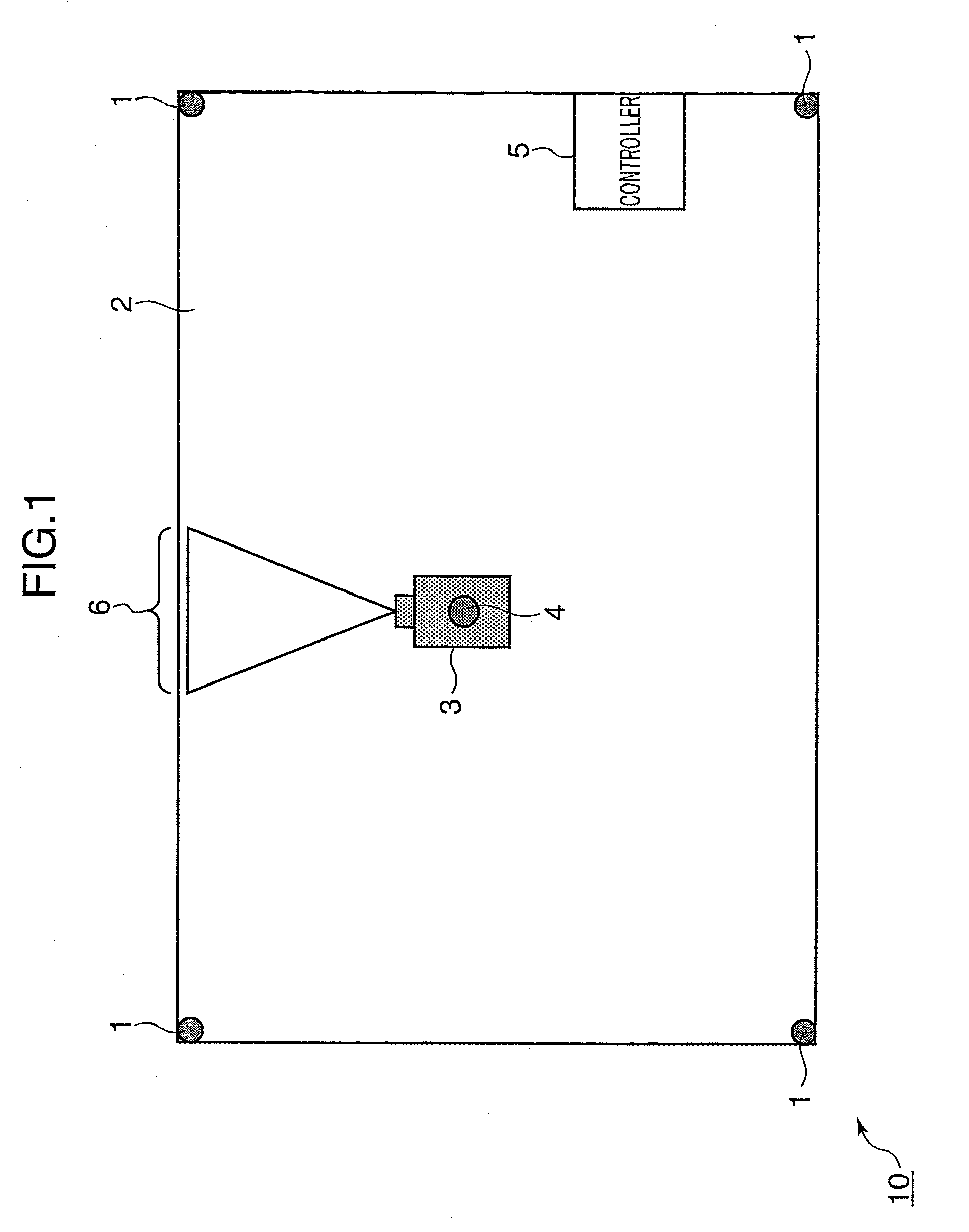
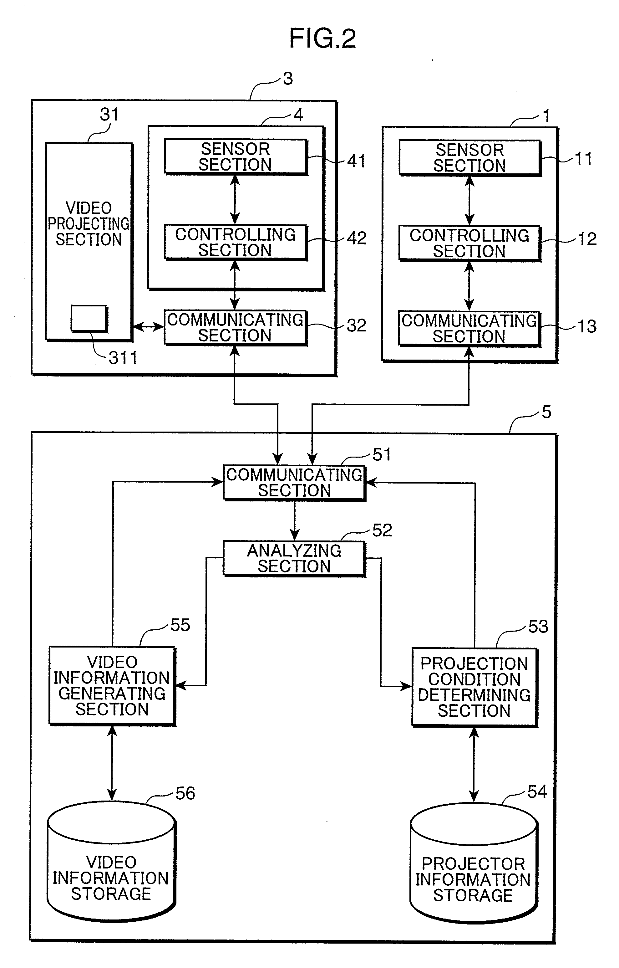
[0025]FIG. 1 is a diagram showing a schematic construction of a projector system according to the first embodiment of the present invention. The projector system 10 according to this embodiment is provided with a mobile projector (projector) 3, fixed position sensors 1 installed in a three-dimensional display space 2 where a video is displayed by the projector 3, and a position sensor 4 mounted in the projector 3 and a controller 5.

[0026]In the projector system 10 according to this embodiment, a plurality of fixed position sensors 1 are installed in the display space 2 where a video is d...

second embodiment

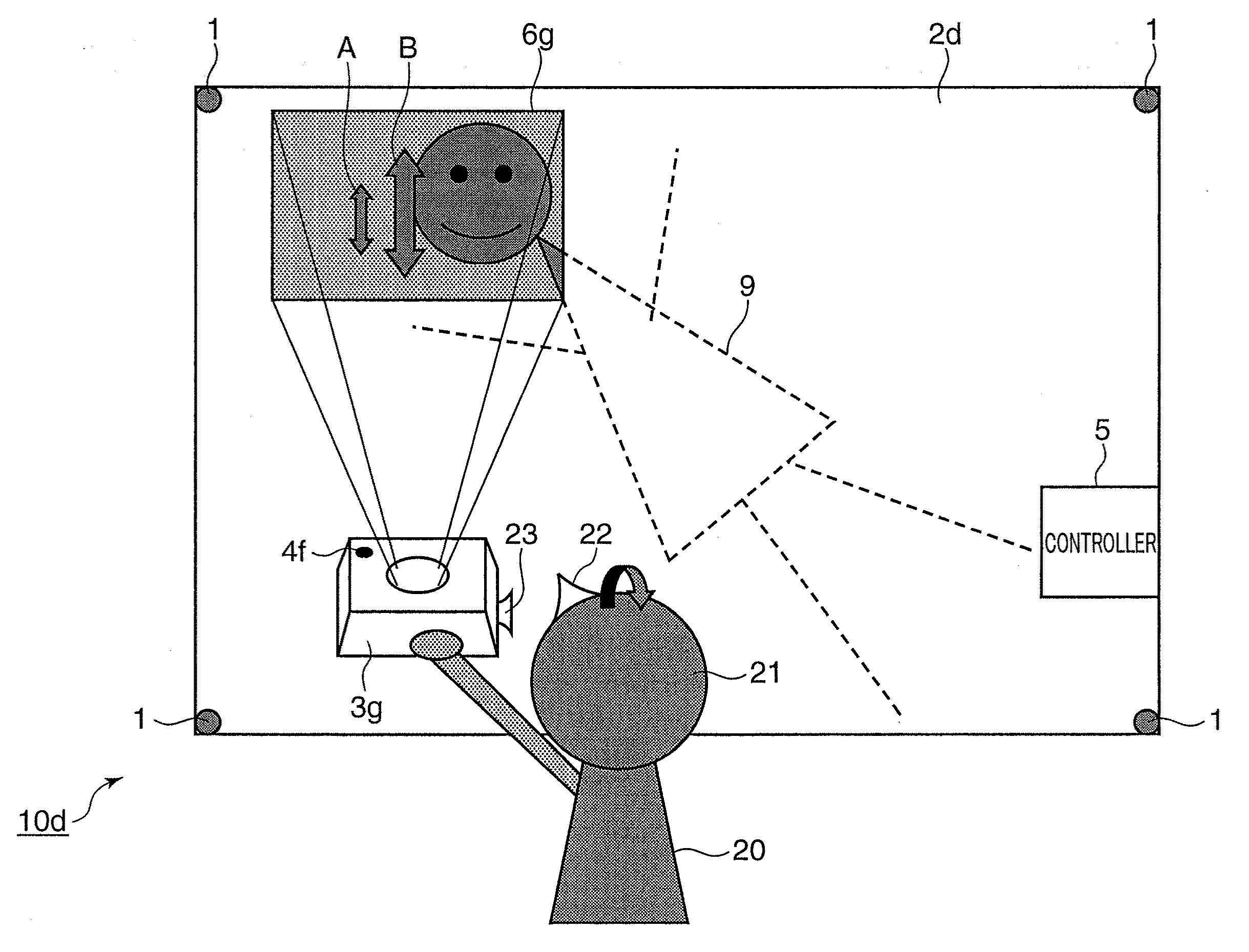
[0056]Next, a second embodiment of the present invention is described. This embodiment is an example in which the projector of the above first embodiment is applied to a mobile projector portable by a user. According to this embodiment, it becomes possible to display a video at an arbitrary position without selecting an installation position of the projector by utilizing a light and small mobile projector. FIG. 4 shows a schematic construction of the projector system according to this embodiment. FIG. 4 shows a state of projection by the mobile projector. This embodiment is described below with reference to FIGS. 1 to 3.

[0057]A projector system 10a according to this embodiment is, as shown in FIG. 4, provided with a mobile projector 3a, fixed position sensors 1 installed in a three-dimensional display space where a video is displayed by the projector 3a, a position sensor 4a mounted in the projector 3a and a controller 5.

[0058]In the projector system 10a of this embodiment, a video ...

third embodiment

[0065]Next, a third embodiment of the present invention is described. This embodiment is an example including a plurality of projectors of the above first embodiment. FIG. 5 shows a schematic construction of a projector system according to this embodiment. FIG. 5 shows a state of projection by the plurality of projectors. This embodiment is described below with reference to FIGS. 1 to 3.

[0066]A projector system 10b according to this embodiment is, as shown in FIG. 5, provided with mobile projectors 3b, 3c, fixed position sensors 1 installed in a three-dimensional display space 2b where videos are displayed by the projectors 3b, 3c, a position sensor 4b mounted in the projector 3b, a position sensor 4c mounted in the projector 3c and a controller 5.

[0067]In the projector system 10b shown in FIG. 5, position information of the mutual projectors 3b, 3c is important in the case where the plurality of projectors 3b, 3c project videos to corresponding irradiation positions 6b, 6c. In this...


PUM


Abstract

A projector system is provided with at least one projector mobile in a specified space and adapted to project a video to a projection area included in the specified space in accordance with inputted video information, a plurality of position sensors each including a position detecting section for detecting a positional relationship of the projector with the projection area and arranged in a specified positional relationship with the specified space, and a controller for controlling a video to be projected from the projector to the projection area based on detection results by the position detecting sections of the plurality of position sensors.

Description

FIELD OF TECHNOLOGY[0001]The present invention relates to a projector system using a mobile projector and a video projection method thereof.DESCRIPTION OF THE BACKGROUND ART[0002]There is known a projector in which a small-size projection unit and a direction sensor or an acceleration sensor are incorporated into a helmet (patent literatures 1, 2). This is constructed such that a facing direction of the projector is detected by the sensor incorporated in the projector and a display image is projected while being appropriately changed based on detection information.[0003]In another projector, there is known a method for optimizing a projected image from image information by taking in an image projected from the projector again (patent literature 3). By this method, the display information of the image projected by the projector is obtained by a CCD or the like, and the display image is projected while being appropriately changed based on that information.[0004]There is also known a m...

Claims


Application Information

Patent Timeline
IPC IPC(8): H04N3/26
CPCG03B21/14H04N9/3173H04N9/3197H04N9/3185H04N9/3194H04N9/3182G03B35/20G03B37/04
Inventor MIZUUCHI, KIMINORIYAMAMOTO, KAZUHISA
Owner PANASONIC CORP
Why Eureka
Try Eureka