
Showcase

a technology for a display chamber and a display chamber is applied in the field of display chambers to achieve the effects of preventing or suppressing deterioration and failure of led illumination members, effectively lighting the inside of the display chamber, and reducing the cost of work

Inactive Publication Date: 2009-08-20
SANYO ELECTRIC CO LTD
View PDF6 Cites 11 Cited by
  • Summary
  • Abstract
  • Description
  • Claims
  • Application Information

AI Technical Summary

Benefits of technology

[0008]The present invention has been developed to solve the conventional technical problems. An object of the present invention is to provide a showcase capable of improving the appearance of an illumination apparatus itself and improving an illumination effect produced by the illumination apparatus.
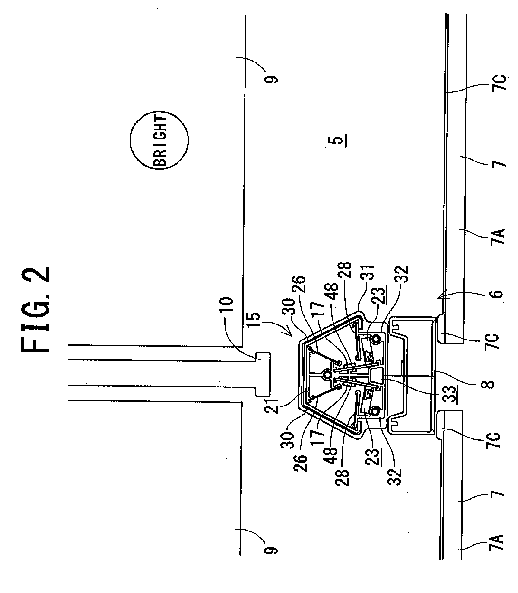
[0014]According to the first aspect of the present invention, in the showcase in which the inside of the display chamber disposed in the main body is illuminated by the illumination apparatus, the illumination apparatus includes the LED illumination member having the LED element, and the holding member attached to the main body to hold the LED illumination member, and the holding member includes the lead wire receiving portion to receive the lead wire of the LED illumination member. Therefore, the lead wire of the LED illumination member can easily be received in the lead wire receiving portion of the holding member.
[0015]In consequence, it is possible to eliminate a disadvantage that the lead wire is carelessly pulled during maintenance of the LED illumination member or the like, whereby safety can be improved. Furthermore, the lead wire can be hidden to improve appearance.
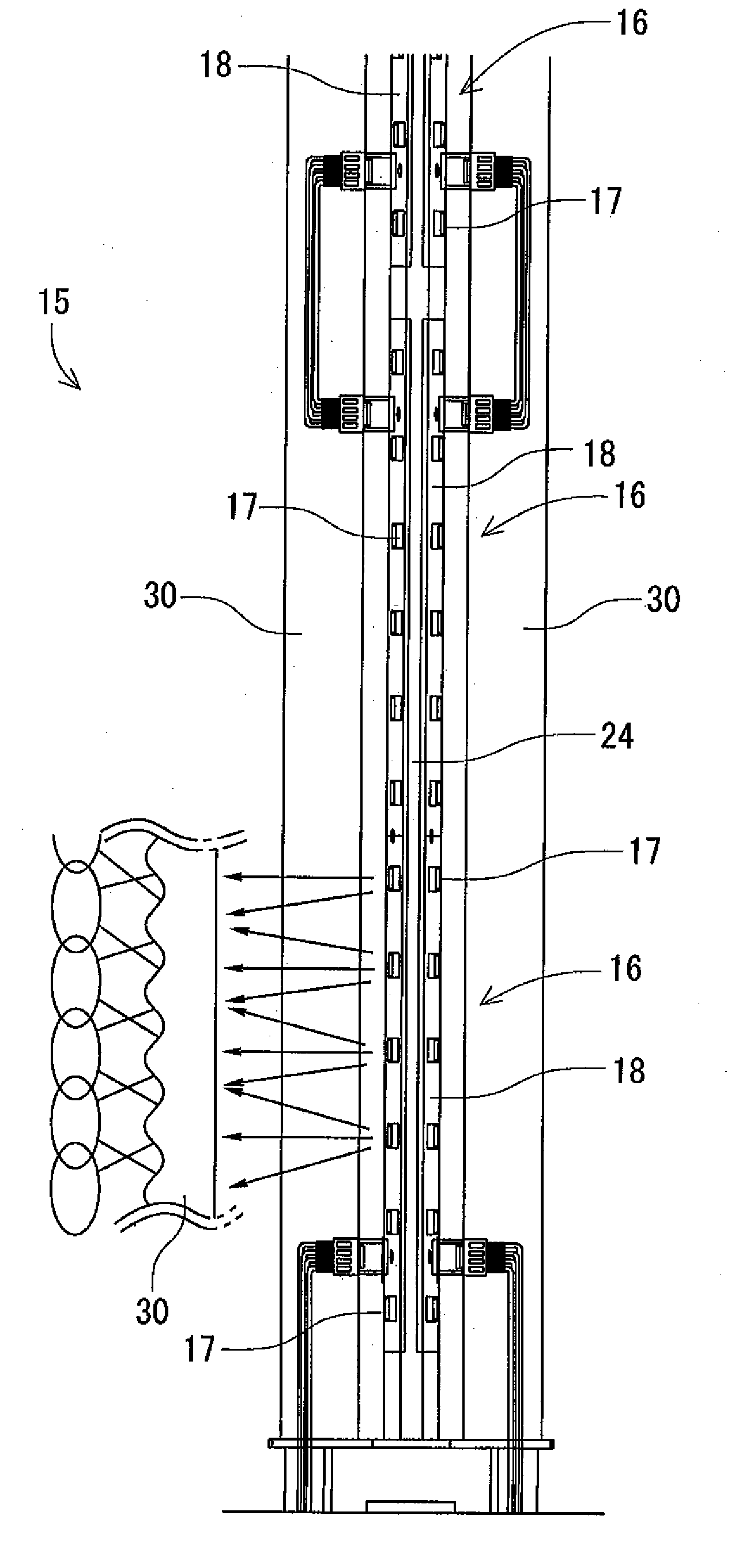
[0016]According to the second aspect of the invention, in addition to the first aspect of the invention, the LED illumination member includes the plurality of LED elements arranged in the row, the shade is attached to the holding member at the position in the irradiating direction of the light from the LED elements, and the shade has a wave-like sectional shape extending in the longitudinal direction of the row of the LED elements. Therefore, intense irradiation light from the LED elements can be diffused by the shade. Moreover, the shade refracts the light in the longitudinal direction of the row of the LED elements, and hence the feeling of discontinuity of the light can be reduced. In consequence, the appearance can be improved.
[0018]According to the fourth aspect of the invention, in addition to the second or third aspect of the invention, the holding member is provided with the pair of reflectors positioned on both the sides of the irradiation path of the light from the LED elements to the shade so that the reflectors are disposed away from each other as the distance from the LED elements increases. Therefore, the irradiation light from the LED elements can be reflected by the reflectors to effectively illuminate the inside of the display chamber.
[0019]According to the fifth aspect of the invention, in the respective aspects of the invention, the LED illumination member includes the substrate provided with the plurality of LED elements on the surface thereof, the holding member is made of the metal, and the holding member is provided with the radiation ribs which abut on the positions corresponding to the backsides of the LED elements on the back surface of the substrate. Therefore, heat from the LED elements can smoothly be radiated through the metal holding member. In consequence, deterioration and failure of the LED illumination member can be prevented or suppressed.

Problems solved by technology

However, the fluorescent lamp used as an illumination apparatus in the conventional showcase has to be replaced owing to a decrease in luminance or a fault of lighting due to aging.
As a result, a user is forced to perform a replacement work of the fluorescent lamp, which causes a problem that the work is cumbersome.
Further, the fluorescent lamp contains mercury, which causes a problem that the used fluorescent lamp cannot easily be discarded.
Moreover, lead wires must be connected to the respective fluorescent lamps for power supply thereto, which causes problems that assembly workability is poor and that the number of the parts, and production cost increase.
Furthermore, the fluorescent lamps use an alternate current, and hence flicker, which causes a problem that eyes are adversely affected.
However, the shade is made of a translucent, colorless and transparent material to secure light transmittance, the lead wires are therefore seen through the shade from the outside, and there is a problem of marring appearance.
Particularly in the illumination apparatus using the LED elements, unlike the fluorescent lamps, the apparatus is provided on the substrate, and it is therefore difficult to hide the lead wires from the outside by the illumination apparatus itself.
Moreover, when the LED illumination apparatus is constituted of a plurality of LED illumination members and the illumination members are provided so that their attachment positions can be freely changed, there is inconvenience that the lead wires disturb a position changing work.
Thus, light passing through the shade is constituted by the rows of intense point light sources, and is inconveniently glaring.

Method used


Image

  • Showcase
  • Showcase
  • Showcase

Examples


Embodiment Construction

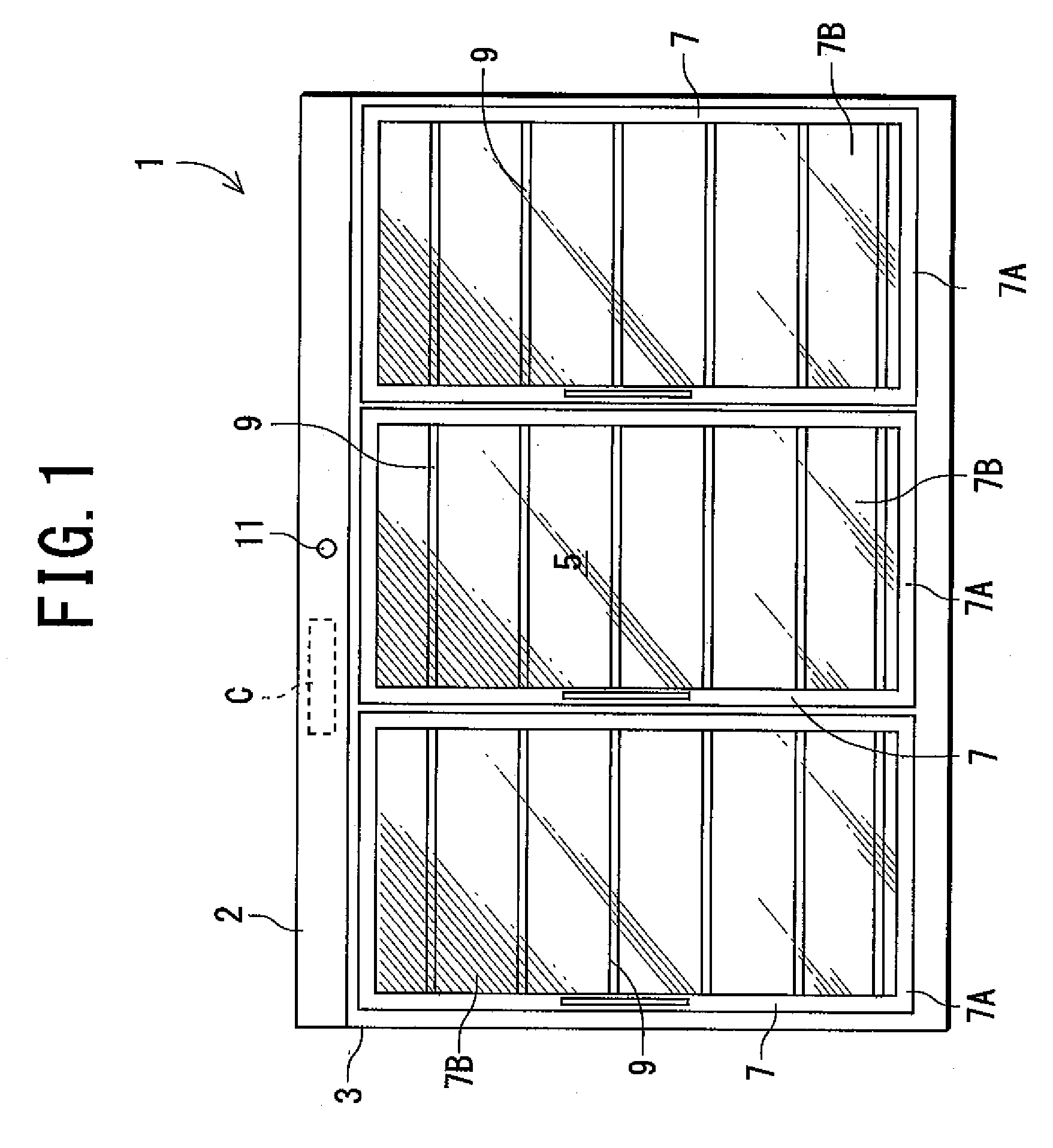
[0025]Hereinafter, an embodiment of the present invention will be described in detail with reference to the drawings. FIG. 1 shows a front view of a showcase 1 to which the present invention is applied, and FIG. 2 shows a partially enlarged sectional view of the showcase 1. The showcase 1 is a low-temperature showcase to be installed in a supermarket, a convenience store or the like, and a main body is constituted by an insulating box member (an insulating wall) 2 whose front face is open.

[0026]The insulating box member 2 is constituted of an outer box 3 made of steel plates and opened at the front face thereof; a unshown inner box made of steel plates or a hard resin, opened at the front face thereof and incorporated in the outer box 3 with a space left therein; and an insulating material made of foamed polyurethane charged in a foamed state between the outer box 3 and the inner box.

[0027]A display chamber 5 is disposed in this inner box, and a front opening 6 of the display chambe...


PUM


Abstract

An object is to provide a showcase capable of improving the appearance of an illumination apparatus itself and improving the illumination effect produced by the illumination apparatus. In the showcase in which the inside of a display chamber disposed in a main body is illuminated by an illumination apparatus, the illumination apparatus includes an LED illumination member having an LED element, and a holding member attached to the main body to hold the LED illumination member, and the holding member includes a lead wire receiving portion for receiving a lead wire of the LED illumination member.

Description

BACKGROUND OF THE INVENTION[0001]The present invention relates to a showcase in which the inside of a display chamber disposed in a main body is illuminated by an illumination apparatus.DESCRIPTION OF THE RELATED ART[0002]Heretofore, in a showcase of this kind, particularly in a showcase in which a front opening of a display chamber is openably closed by a see-through door and illumination devices are vertically attached to a main body inwardly from the edge of an opening, a vertical pillar is disposed at the center of a front opening edge or on each side of the opening edge, and a fluorescent lamp is attached to the rear surface of this pillar to illuminate the inside of the display chamber from the front side (e.g., see Japanese Patent Application Laid-Open No. 8-224150 (Patent Document 1) and Japanese Utility Model Registration No. 2546302 (Patent Document 2)).[0003]However, the fluorescent lamp used as an illumination apparatus in the conventional showcase has to be replaced owi...

Claims


Application Information

Patent Timeline
Patent Type & Authority Applications(United States)
IPC IPC(8): A47F11/10
CPCA47F3/001F21S4/003F21S4/008F21V1/00F21Y2101/02F21V7/005F21W2131/305F21W2131/405F21V7/0025F21S4/20F21S4/28F21Y2115/10A47F3/04A47F11/10
Inventor OTSUKI, ATSUOAMARI, YOICHIOKETANI, TETSUYASHIBUSAWA, SAKUMI
Owner SANYO ELECTRIC CO LTD
Learn More