Generating drive signals for a synchronous rectification switch of a flyback converter

a technology of synchronous rectification switch and drive signal, which is applied in the direction of electric variable regulation, process and machine control, instruments, etc., can solve the problems of generating significant costs, 888,728 b2 is the higher component effort meaning also higher cost, and the overall effort of the sub-circuit to drive the synchronous rectifier switch on the secondary side of the transformer is very high, so as to reduce the cost of the circuit to drive the synchronous rectifier mosfet, the power loss of the actively clamp

Inactive Publication Date: 2009-08-20
SIGNIFY HLDG BV
View PDF17 Cites 20 Cited by
  • Summary
  • Abstract
  • Description
  • Claims
  • Application Information

AI Technical Summary

Benefits of technology

[0018]Advantageous embodiments of the present invention have the advantage of a minimum effort to sense electrical signals.
[0019]A further advantage of certain embodiments of the present invention is that the cost of the circuit to drive the synchronous rectifier MOSFET can be significantly reduced; in addition thereto, also the power losses of the actively clamped bidirectional flyback converter with synchronous rectification can be reduced. The latter advantage can be used to reduce the effort for thermal management, i.e. to transfer the heat out of the preferably closed housing of the circuit arrangement of the present invention.

Problems solved by technology

This overall effort of sub-circuits to drive the synchronous rectifier switches on the secondary side of the transformer is very high and generates significant costs.
The greatest disadvantage of U.S. Pat. No. 6,888,728 B2 is the higher component effort meaning also higher cost.
The component count of this known circuit is very high; apart from that, the load resonant converter includes a second power transformer plus a shunt resistor both generating additional power losses and thus increasing the thermal management effort.
The greatest disadvantage of JP 2005-198438 A is the use of a second power transformer to monitor the input current of the load resonant circuit on the secondary side of transformer; this generates significant loss in the second power transformer.

Method used


Image

  • Generating drive signals for a synchronous rectification switch of a flyback converter
  • Generating drive signals for a synchronous rectification switch of a flyback converter
  • Generating drive signals for a synchronous rectification switch of a flyback converter

Examples


Embodiment Construction

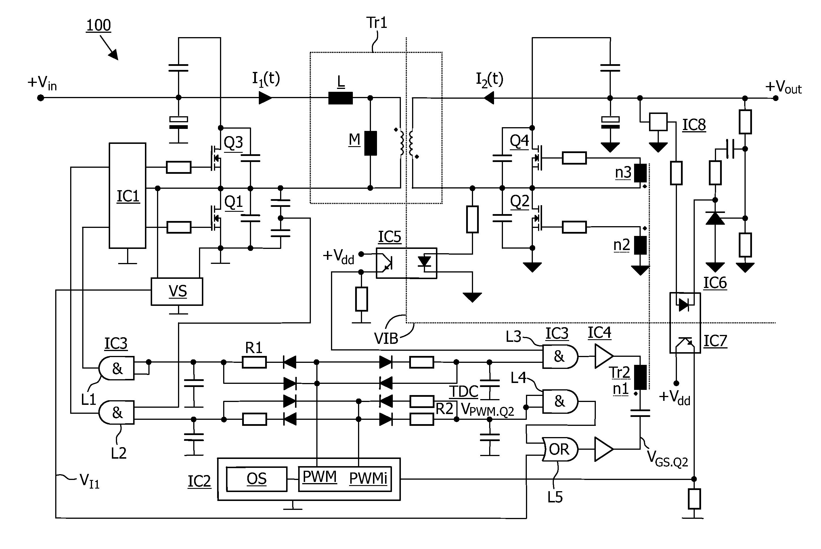
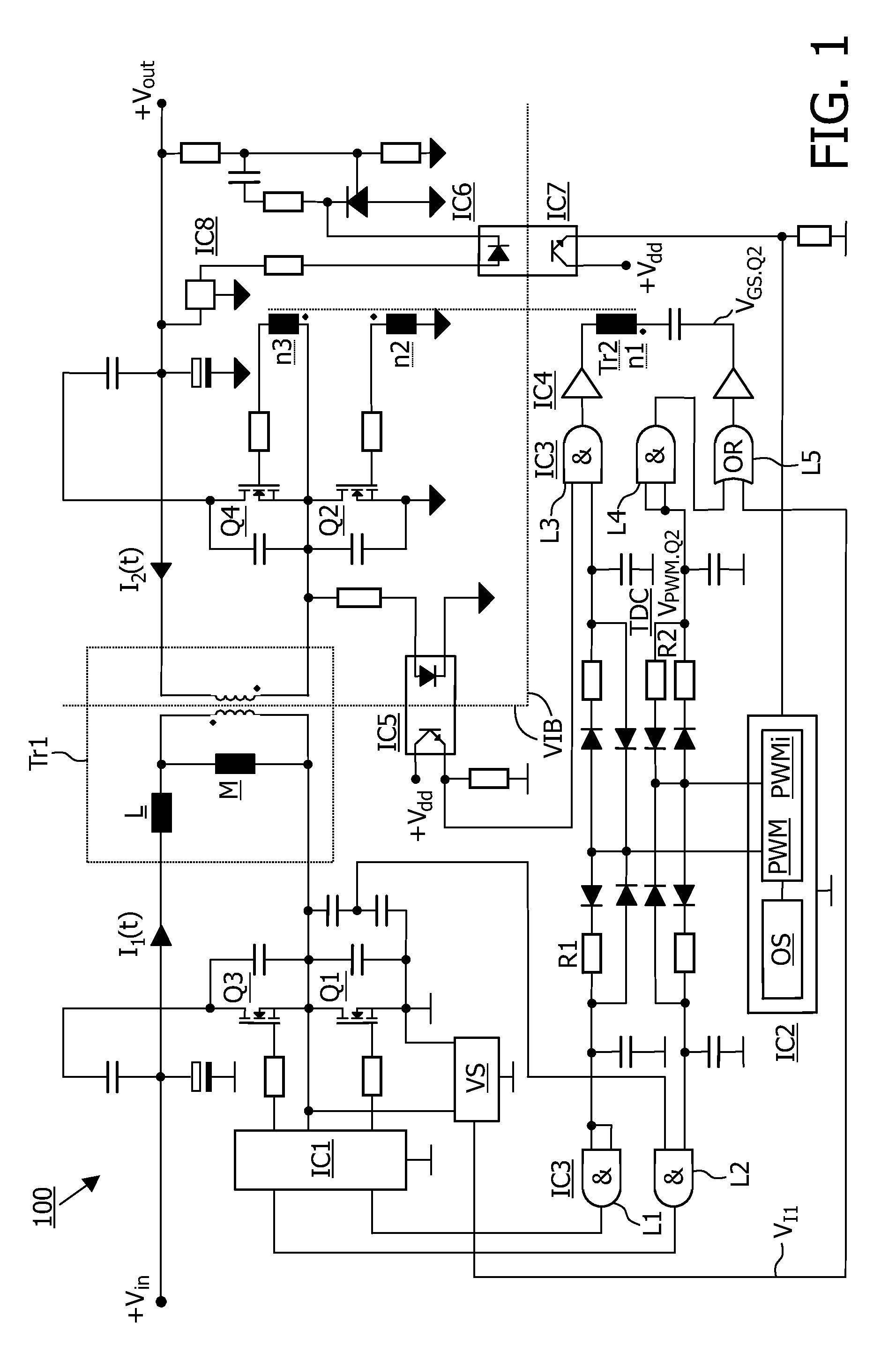
[0028]FIG. 1 shows a block diagram of a preferred embodiment of the circuit arrangement 100 according to the present invention. The circuit arrangement 100 comprises an actively clamped bidirectional flyback converter with four power semiconductors Q1, Q2, Q3, Q4; each of these power semiconductors Q1, Q2, Q3, Q4 is implemented as a transistor unit, in particular as a metal-oxide semiconductor (MOS) or as a metal-oxide semiconductor field effect transistor (MOSFET).

[0029]Two of these transistors, namely the first transistor Q1 and the third transistor Q3 are located on the primary side of a power transformer Tr1; the other two of these transistors, namely the second transistor Q2 and the fourth transistor Q4 are located on the secondary side of the power transformer Tr1. The second transistor Q2 acts as synchronous rectifier; the fourth transistor Q4 is a semiconductor switch or active clamping switch designed to actively confine or to actively delimit the voltage load of the synchr...


PUM


Abstract

In order to further develop a circuit arrangement (100) as well as a method for generating at least one drive signal for at least one synchronous rectification switch of at least one flyback converter in such way that an improved and simpler thermal management can be combined with a significant cost reduction as well as with a higher efficiency, it is proposed to generate the drive signal for said synchronous rectification switch as a function of at least one oscillating signal controlling the synchronous rectification switch, of at least one constant delay time, of at least one variable delay time, and of at least one Boolean OR function.

Description

FIELD OF THE INVENTION[0001]The present invention relates to a circuit arrangement for generating drive signals for a synchronous rectification switch of a flyback converter. The present invention further relates to a method for generating at least one drive signal for at least one synchronous rectification switch of at least one flyback converter, in particular at least one actively clamped bidirectional flyback converter.BACKGROUND OF THE INVENTION[0002]An actively clamped bidirectional flyback converter is disclosed in the article “Experimental Analysis Of A Flyback Converter With Excellent Efficiency” as presented by U. Boeke, D. Itzenga, K. Rigbers, and R. W. De Doncker in Proceedings of Applied Power Electronic Conference (APEC) from Mar. 19 to 23, 2006, in Dallas, Tex.[0003]This actively clamped bidirectional flyback converter is based on the reference document “Actively-Clamped Bidirectional Flyback Converter” by Gang Chen, Yim-Shu Lee, S. Y. Ron Hui, Dehong Xu, Yousheng Wan...

Claims


Application Information

Patent Timeline
Patent Type & Authority Applications(United States)
IPC IPC(8): H02M3/335
CPCY02B70/1475H02M3/33592Y02B70/10H02M3/28H02M3/155
Inventor BOEKE, ULRICH
Owner SIGNIFY HLDG BV
Why Eureka
Try Eureka