Tomosynthetic image reconstruction method and apparatus

a reconstruction method and image technology, applied in the field of tomosynthetic image reconstruction method, can solve the problems of complicated detection ability of such tumors and noisy individual 2d projection images

Active Publication Date: 2009-08-20
SIEMENS HEALTHCARE GMBH
View PDF9 Cites 9 Cited by
  • Summary
  • Abstract
  • Description
  • Claims
  • Application Information

AI Technical Summary

Benefits of technology

[0007]An object of the present invention is to provide a tomosynthetic image reconstruction method with which it is possible to generate low-noise tomosynthetic 3D x-ray

Problems solved by technology

Since the tissue layers lying atop one another in the direction of the x-ray beam are superimposed in such a projection, strongly absorbent benign structures can overlap a malignant tumor and complicate the ability to detect such a tumor.
In the generation of the individual 2D projection images, the total dose allowed for a mammography exposure cannot be exceeded, such that these individual 2D projection images must be acquired with a dose that amounts to only a fraction of the permissible total dose (dep

Method used


Image

  • Tomosynthetic image reconstruction method and apparatus
  • Tomosynthetic image reconstruction method and apparatus
  • Tomosynthetic image reconstruction method and apparatus

Examples


Embodiment Construction

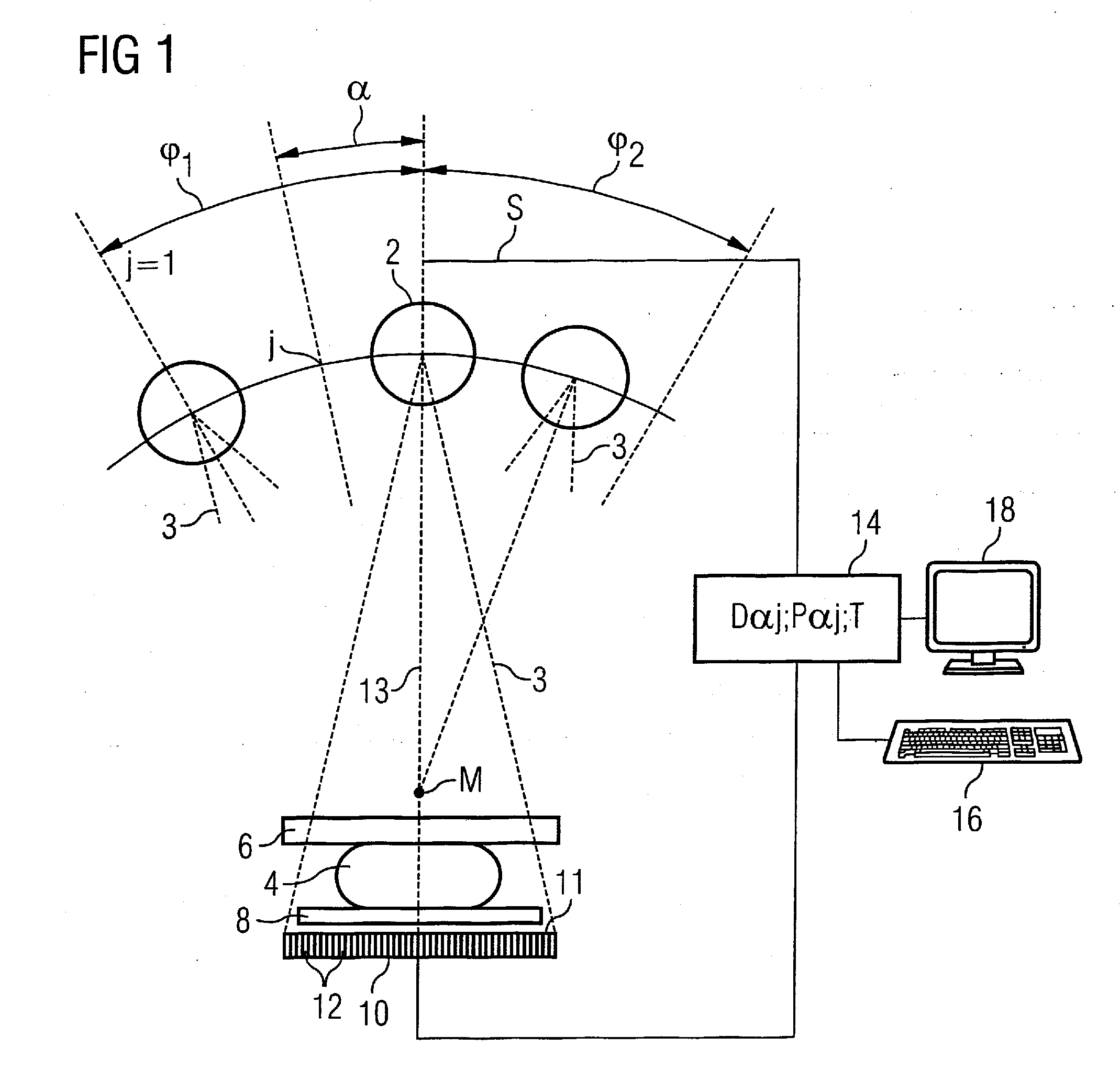
[0023]According to FIG. 1, the device (a mammography apparatus in the exemplary embodiment) comprises an x-ray tube 2 to generate x-ray beams 3 that pass through an examination subject 4. The examination subject 4 is a female breast that is held between a compression plate 6 and a support plate 8. The x-rays 3 passing through the examination subject 4, the compression plate 6 and the support plate 8 are received by a large-surface digital x-ray detector 10 that is composed of a number of individual detectors 12 arranged in a matrix array. The acquisition surface 11 of the x-ray detector 10 is parallel to the compression plates 6, 8.

[0024]The x-ray tube 2 is mounted such that it can varied in terms of location in a limited region relative to the examination subject and, for example, can be pivoted into different angle positions j=1 . . . n in a limited angle range φ1, φ2 around an axis M perpendicular to the plane of the drawing, such that 2D projection data sets Dαj for different pr...


PUM


Abstract

To generate a tomosynthetic 3D x-ray image composed of a number of slice images, a tomosynthetic 3D intermediate image composed of a number of slice images is reconstructed from 2D projection images that have not been noise-filtered. The microcalcium regions contained in these slice images are segmented, and one or more subject slice images relevant to these microcalcium voxels are determined for each microcalcium region. The microcalcium voxels belonging to the segmented microcalcium region in this subject slice image or in these subject slice images are projected forwards in the 2D projection images, and the microcalcium pixels associated with these microcalcium voxels are marked in the 2D projection images. Noise-filtered 2D projection images are subsequently generated by subjecting the microcalcium pixels of the 2D projection images to no noise filtering or a noise filtering that leads to a noise reduction reduced relative to the remaining image regions. The tomosynthetic 3D x-ray image is then calculated from the 2D projection images that have been noise-filtered in this manner.

Description

BACKGROUND OF THE INVENTION[0001]1. Field of the Invention[0002]The present invention concerns a tomosynthetic image reconstruction method, in particular such a method suitable for mammography, in which a tomosynthetic 3D x-ray image is assembled from a number of digital 2D projection images acquired from various projection angles. Moreover, the invention concerns a diagnostic apparatus operating with such a method.[0003]2. Description of the Prior Art[0004]Mammography is an x-ray examination of the female breast, with the goal of detecting tumors in as early a stage as possible. Through steady improvement in mammography methods it is intended to generate x-ray images with good clarity in order to differentiate benign from malignant variations, and to reduce the number of incorrect findings (i.e. the number of suspicious findings that are caused by non-malignant variations) and the number of undetected malignant tumors. In conventional x-ray mammography, a two-dimensional single ima...

Claims


Application Information

Patent Timeline
IPC IPC(8): A61B6/04
CPCA61B6/502G06T11/006G06T11/005
Inventor FISCHER, DANIELLUDWIG, JASMINA
Owner SIEMENS HEALTHCARE GMBH
Why Eureka
Try Eureka